ku637
Advanced Member level 4
Dear Geeks,
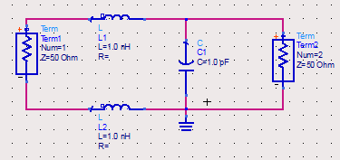
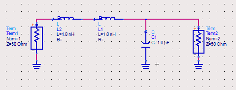
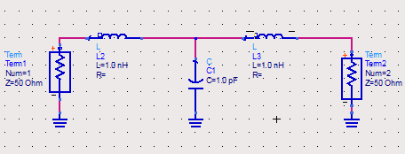
I have got a simple filter structure..like shown below..
I would like to analyse its input impedance in Agilent ADS .. can anyone please tell me how to do it?
Input is the inductor side.. Output is the capacitor side..
Problem i face is ..
1.I connect port 1 with 50Ohm termination in between the input side inductors & port 2 on the output side across the capacitor ..
2.Now how to properly connect the GND symbol?
3.If i connect it at both input and output ports it will short the L2 inductor
Can somebody please help me...??
Regards
I have got a simple filter structure..like shown below..
HTML:
INPUT    L1
------(((((()--------------------------       OUTPUT
                          |
                          |
                         __C1
                         ---
             L2          |
------(((((()-------------------------
I would like to analyse its input impedance in Agilent ADS .. can anyone please tell me how to do it?
Input is the inductor side.. Output is the capacitor side..
Problem i face is ..
1.I connect port 1 with 50Ohm termination in between the input side inductors & port 2 on the output side across the capacitor ..
2.Now how to properly connect the GND symbol?
3.If i connect it at both input and output ports it will short the L2 inductor
Can somebody please help me...??
Regards
Last edited: