Continue to Site

Welcome to EDAboard.com

Welcome to our site! EDAboard.com is an international Electronics Discussion Forum focused on EDA software, circuits, schematics, books, theory, papers, asic, pld, 8051, DSP, Network, RF, Analog Design, PCB, Service Manuals... and a whole lot more! To participate you need to register. Registration is free. Click here to register now.

[FGPA] Expansion header of DE2 board as input.

Status
Not open for further replies.

jesslyn993

Newbie level 5
Joined
Jan 21, 2015
Messages
9
Helped
0
Reputation
0
Reaction score
0
Trophy points
1
Activity points
76
Hi, this is my mini project which i will use expansion header of DE2 board as my input.
1.JPG

I am using the VCC and ground from the GPO1 (expansion header block) where the signal input also at the same expansion header block. With only one input, it shows no error.

However, when i needed to use two input and i used the same power pin and ground pin, it doesn't work. When i pressed on one button, the other one will automatically light up as well.

The following is the simple code i use to test the input. I wish anyone could tell me what should i do as i need more inputs.

module test (out1,out2,in1,in2,yup,no,clk);
input in1,in2,yup,no,clk;
output reg out1=0,out2=0;


always@(posedge clk)
begin
if (in1)
out1<=1;
else
out1<=0;


if (in2)
out2<=1;
else
out2<=0;

end
endmodule
 

First point, don't feed 5V signals to FPGA input ports. DE-2 is protected by series resistors and schottky diodes, but the regular input voltage range is still exceeded.

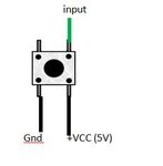
Secondly, I don't understand how you connected the button. The sketched part isn't a double-throw switch. Instead it looks like a single N.O. contact with internal bridges, the same type is used on DE-2 board, by the way.

The best way to connect a switch or push button to an FPGA input is to use a pull-up resistor and pull the input to ground by the cloased switch. Review the DE-2 schematic how they do it. An internal pull-up resistor is usually sufficient.

Seeing the switch event on both inputs could be due to floating inputs. I suggest to try with the known working on board push-buttons first.
 
Hi, Thanks for your reply.

my 5V signal is from expansion header itself. This doesn't work as well?
The push button i am using is definitely not double-throw switch. It is just a normal switch. Did you means this kind of push button doesn't work?

2.JPG

I found out that when the signal wire was leave without connecting to power supply or ground, it will trigger the signal and the led will light up. I tried to used the switch to pull the signal to ground when the push button is being pressed. However both LEDs were being lighted up and couldn't being shut down.

Thanks for your advice, i have already tested using on board push-buttons. With only DE2 manual, i didn't really understand how the schematic can help me to connect my circuit. If you may, please bear with me and tell me more.
 

The schematic in post #1 and the latest switch circuit obviously don't fit together. What's the connection of GND and +5V?
Perhaps you'll want to correct the schematic reflecting the actual connection?

Switching to ground is O.K., but there must be a pull-up resistor (preferably to 3.3V node), otherwise the input would float to undefined level as long the switch is open. Or enable a FPGA internal weak pull-up resistor for the respective pin.
 
Thanks for your help.
It works after i connect the signal pin to 3.3V with a resistor.
 

Status
Not open for further replies.

Part and Inventory Search

Welcome to EDABoard.com

Sponsor

Back
Top