Continue to Site

Welcome to EDAboard.com

Welcome to our site! EDAboard.com is an international Electronics Discussion Forum focused on EDA software, circuits, schematics, books, theory, papers, asic, pld, 8051, DSP, Network, RF, Analog Design, PCB, Service Manuals... and a whole lot more! To participate you need to register. Registration is free. Click here to register now.

[SOLVED] Few questions about making a PICkit 2 clone

Status
Not open for further replies.

GuiRitter

Junior Member level 1
Joined
Oct 19, 2011
Messages
17
Helped
0
Reputation
0
Reaction score
0
Trophy points
1,281
Activity points
1,560
Hi everyone.

I want a PIC programmer, but I live in a city with limited options regarding electronics, specially microcontrollers. Building one will be much cheaper than buying one, and I should have built one when I made my mechatronics technician's course, but didn't because I didn't liked the design, so I want to do it now.

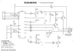
After a lot of search I settled in **broken link removed** design. I guess it's as simple as it could get. I only want it to program the most common models, nothing more.

But there are some things in that link that I'd like to understand more clearly before ordering the remaining parts:

1. As I understood, the MCLR, GND, PGD and PCG of J1 are connected to the same-named pins of the target PIC, and nothing else. No need to power it separately. Am I right?

2. I can't obtain some of the components, so I'd like to know if I can make the following switches:
C1 and C2 to 22 pF or 27 pF;
C4 to 33 µF;
C5 to 2,2 µF.

3. What is D2 supposed to be? I know it's a diode, but there's no model.

4. Does the "FLAT" on the transistors' names mean something important?

I think the rest will be easy. Until I get to turn it on and test it...

Thanks in advance.
 

1. The programmer itself is powered from USB. That target device must be supplied from its own power supply during programming, since this programmer circuit cannot provide power to the target.

2. C1,2 - yes, either should be good. C4 - yes. C5 - Usually that would be 220nF (nanofarad) for Vusb, although the original PICKit 2 uses 470nF. Not sure why this design has 2uF. If 2uF works, then 2.2uF probably will, but I use 220nF on Vusb.

3. It's a Schottky diode. The original uses a surface mount BAT54, I think the exact wired equivalent is BAT85 but any general Schottky rectifier diode will probably do.

4. No idea - A BC547 is a BC547. I would ignore the FLAT.

Good luck with the build!
 
Last edited:
1. Correct - but the PicKit will first check for an existing supply and use it. If it doesn't see a supply, it tries to provide one itself. Bear in mind that when programming in-circuit there may be other devices drawing current from the supply lines and the PicKit may not be able to cope with the load.

2. C1 & C2 are 0.1uF and 22pF respectively on my schematic. If you mean the two caps across the crystal, yes 27pF will probably work OK.
C4 is 0.1uF on my schematic, can you clarify which capacitor you mean.
C5 is 10uF on my schematic, again it doesn't seem to match yours.

3. Strangely, there doesn't seem to be a D2 on my schematic, although there is a D1, 3 and 4!

4. No mention of 'FLAT' on my schematic at all.

I should point out I'm using the official PicKit 2 schematic as supplied by Microchip, reference DS51553E.

Brian.
 

Betwixt, the schematic in question is in this link:

**broken link removed**

It's a little hidden in GuiRitter's post. Some of your comments probably won't apply because the circuit is modified a fair bit.
 

Thanks FoxyRick, I didn't spot the link.

I would be hesitant to call that a clone, it is very different to the original !!

Brian.
 

GuiRitter

After a lot of search I settled in this design. I guess it's as simple as it could get. I only want it to program the most common models, nothing more.

But there are some things in that link that I'd like to understand more clearly before ordering the remaining parts:


Hi,

If you search this forum you will find many clone versions of the Pickit2.
Some even have details of a very basic programmer you can use to program up the 18F2550 from a serial or parallel port.

This is my simple version which might help you identify the parts better.

The transistors, always check the pin outs for the ones you buy locally as some manufacturers use differerent packages / layouts.
 

Attachments

  • minipk2.jpg
    minipk2.jpg
    66.6 KB · Views: 72
  • pickit2_Lite.pdf
    44.6 KB · Views: 62

Yay, so many answers in so little time! I made the right choice when I posted here. Thanks for all the answers, I can almost order the components now. One little question remains, that I almost felt like ignoring and went to order the others. But since you've been so helpful I'll wait a little more. See below.

3. It's a Schottky diode. The original uses a surface mount BAT54, I think the exact wired equivalent is BAT85 but any general Schottky rectifier diode will probably do.

So I suppose a BAT43 will do the trick? It's the only schottky available for purchase, and I checked their datasheets and they seem pretty equivalent. I can get the BAT85, but it would have to be from another vendor and everything will be much more expensive.


Less priority things:


1. The programmer itself is powered from USB. That target device must be supplied from its own power supply during programming, since this programmer circuit cannot provide power to the target.
1. Correct - but the PicKit will first check for an existing supply and use it. If it doesn't see a supply, it tries to provide one itself.
I thought that these two answers were conflicting, but then I decided to post the following quote, from the link from my first post, and then I understood.
What I removed:
(...)
The Vdd circuitry. Hence this programmer can not supply power to the target circuit. I thought this would be a problem for older devices such as 16F628 or 16F877A that, in theory, require Vpp before Vdd, but actually, it works anyway !

From the previous quote, I thought that Vdd was unnecessary, but then I understood that it's the order it was talking about. So I still need to power it. So, is there a problem to use the same power from the programmer (disregarding what is below)?


Bear in mind that when programming in-circuit there may be other devices drawing current from the supply lines and the PicKit may not be able to cope with the load.

Yeah I'm aware of that. I even designed a modular PCB to house the PIC, oscillator crystal, connection to ports and jumpers to ensure safety. Imagine a track on the PCB like this:

PIC ---- ICSP port ---- jumper ---- rest of the circuit


This is my simple version which might help you identify the parts better.

Yeah I saw that one while searching, but I decided on the other one for the smaller part count. I don't really think the LEDs are necessary, and it will draw less current! Thanks for the suggestion anyway.
 

To explain the power situation - the REAL Pickit 2 can supply power to the target device, the clone circuit you show does not have that ability. The real PicKit has a lot of features that are missing from the clone.

Which country are you in that finding parts is so difficult? Possibly other readers can advise on local supply outlets.

Brian.
 

I think that a BAT43 would work; as you say, there's not much difference.

With regards to powering the target PIC from the programmer's power, then provided that you are only powering the target PIC and not the rest of some circuit, I think that would work too.

If you draw too much current (which will come from the USB port) then most likely the PC will just shut off the port and you'll get an annoying 'the USB device has malfunctioned' message. No harm should be done though. It's just a case of how the MPLAB software allocates current to the USB port. The original PICKit can provide target power, so the software must be allocating enough current to the USB port for it to do so.

The difference is, as Betwixt has noted, that the original PICKit can control the VDD to the target PIC. Yours won't be able to control it, other than you manually connecting it.

Are you only interested in programming 5V PIC's?
 
Last edited:
Hi,

As you can see from my diagram in entry # 6 I simply used a standard 1N4148 / 1N914 it works fine, though a schottky type would be better if you are using a laptop with a low usb voltage - any schottky capable of 100ma 50V should be fine.

You will have problems with that design if you try icsp while the target board is powered, there is nothing to stop the voltages meeting - in my diagram D4 is use to prevent that clash.

To overcome the current handling of the Pk2, I modify the icsp socket so that the USB +5v is fed directly to pin 6 of the socket which can then be used to power the user circuit. Believe most desktop usb ports supply 500ma as standard, not sure about laptops etc.

If you want to program 3v3 chips you can add a 3v3 regulator to the whole circuit, however this is when adding on all the extras and making a second programmer to burn the 2550 chip makes the cost of the whole project almost the same price as a full ready made Pickit2 with all its features - personally recommend you buy a genuine one, much the better option.
 

Which country are you in that finding parts is so difficult? Possibly other readers can advise on local supply outlets

Brazil - Rio Grande do Sul - Santa Cruz do Sul

Nation- and state-wise it's not a problem, but in the town I live in, the electronics shops we have are more focused on fixing stuff, not much microelectronics components to make new circuits. But as I was preparing to order the components from our capital, I did noticed I might be able to get most of them locally. I had thought different because the previous designs I considered had rarer components.

Are you only interested in programming 5V PIC's?

Yes. As I said in the first post, I want it as simple as possible. I won't make anything commercial anyway, so why bother?

About powering the target PIC, now that I fully understand what must be made I'll find the best way to do it.

And I believe that's all I need to know. I'll assemble it and if it doesn't go as smoothly as it should I'll make another thread.

Thanks for all the support!
 

You should be able to mail order from http://www.farnellnewark.com.br it's the company I get almost all my parts from although I deal with the European outlets.

That's the other vendor I referred earlier, but from there I have to buy resistors in multiples of 50! On the other hand, soldafria.com.br allows me to buy resistors and other components individually. The downside is that the order must cost at least R$ 10,00, but there's always stuff that is good to have stocked :smile:

UPDATE: went to the local shop with the most diversity and found out that the BC547 and BC557 cost R$ 3,00, while on soldafria.com.br they cost R$ 0,16! Told ya I had limited options.
 
Last edited:

Status
Not open for further replies.

Similar threads

Part and Inventory Search

Welcome to EDABoard.com

Sponsor

Back
Top