Continue to Site

Welcome to EDAboard.com

Welcome to our site! EDAboard.com is an international Electronics Discussion Forum focused on EDA software, circuits, schematics, books, theory, papers, asic, pld, 8051, DSP, Network, RF, Analog Design, PCB, Service Manuals... and a whole lot more! To participate you need to register. Registration is free. Click here to register now.

Ferrite bead in Drain of offline Flyback and Forward SMPS's?

Status
Not open for further replies.
T

treez

Guest
Hi,
A contractor has presented us with some schematics of SMPS’s that he says he’s done at previous companies. He is offering to re-use them, since they are very cheap in terms of low parts count.

These include Offline, 240VAC DCM and BCM Flyback SMPS’s to 125W with vout = 25v.
They also include offline , 240VAC, 1 Transistor forward converters up to 150W.

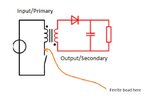
They all have ferrite beads in the drain of the primary switching FET (as attached). Would you agree with me that this is a very poor situation?

I mean, surely, if the drain di/dt is wanting to be reduced, then surely one would increase the series gate resistor? (or is it that the FET may go obsolete, and then the series gate resistor would need value tuning again, so having a ferrite bead there prevents this re-tuning needing to be done?...thats the only reason I can think of to put a ferrite bead in this place.)

Another point is that having a ferrite bead here means you’re breaking an inductive current when the FET switches off…so the FET drain voltage will shoot up higher.
Another point is that Flybacks and forwards have some leakage inductance which is "seen" by the fet as it switches on...so why bother adding a ferrite bead aswell? Isnt this ferrite bead, in this position, simply a throw-back to the old days where CCM boost PFC's only had slow diodes to work with, and some way had to be found to reduce the reverse recovery current spike...that antique SMPS situation is the only one that i can think of where such ferrite beads were warranted?

However, it does occur to me, that as mad as this component is, just maybe, these nice, cheap SMPS’s won’t work on max load if we simply short out this ferrite bead? I mean, due to the lack of other measures to reduce di/dt, these power supplies now rely on this dodgy ferrite bead to reduce FET drain di/dt…just maybe if we short these ferrite beads out then increased noise will get into the control and the power supplies will mal-function.

Isnt a bit like getting up to the top of Mount Everest, opening your lunchbox, and finding that all that’s in there is moldy bread , but having to eat it anyway because you’ll starve if you don’t?
 

Attachments

  • flyback  SMPS with ferrite bead.jpg
    flyback SMPS with ferrite bead.jpg
    33.3 KB · Views: 304
If the FB's added inductance is much lower than the leakage inductance of the transformer, and its ESR at the ringing frequency is properly selected to damp the ringing, then it can be effective. Definitely not my preferred way of doing things, since I generally don't trust FBs to have well-controlled ESR.
 
  • Like
Reactions: treez

    T

    Points: 2
    Helpful Answer Positive Rating

    reza_kamalzadeh

    Points: 2
    Helpful Answer Positive Rating
Thanks, your reply is appreciated, as i know that its difficult to think why this madness has occurred. Thanks for throwing out your thoughts and spending the time. Its certainly helped me to crystallize my own thoughts....
(by the way, sorry, i forgot to say that this FB is not placed in the loop of the RCD clamp)
If the inductance of the FB is much less than the leakage inductance , then i'd say that the FB is a total waste of time, as the leakage inductance would reduce drain current di/dt by itself. As far as damping the ringing at the drain node, its only the resistance of the FB that would help toward that, so why not just put a resistor there?....but no, that is not good....if we want to damp the drain node ringing then we should be putting an RC snubber there from Drain to source of the primary fet.
As discussed, the use of an FB in this way is a throw-back to antique "fast diodes" used in old Boost PFC's , which werent fast diodes at all, and the FB was indeed then needed to slow up the reverse recovery spike. The situation we have here is totally different to that. I am wanting to just remove the ferrite bead all together, (short it out), but some sub-set of Murphy's Law might then come into play.... When you get a circuit designed around a "dodgy technique" like this , then removing that "dodgy technique" might throw a gremlin in there and cause some mal-function.
 
Last edited by a moderator:

One assumes the beads are more lossy than inductive - thus they are good for suppressing VHF ringing and RFI getting from the tab to the h-sink

if they were very inductive and not very lossy at all - then yes - there would be a drain spike at fast turn off ...

good idea to check the bead material ...
--- Updated ---

p.s. also ask the designed to explain the beads - if he cannot clearly explain straight away - then you can assume it is a bit of a fudge additive on their part ...
 
  • Like
Reactions: treez

    T

    Points: 2
    Helpful Answer Positive Rating
One assumes the beads are more lossy than inductive - thus they are good for suppressing VHF ringing and RFI getting from the tab to the h-sink
Would a low value resistor just be better?..its the lossiness that seems to be key here.
Or is it that the bead starts off being inductive and so slows di/dt at first , but then saturates and becomes less inductive and mostly resistive?
Also, is it true its (the bead) is not like "normal" resistance?.....but is the effect of core losses in the bead...which make it "Look" resistive?
 

the bead is all resistive at very high frequencies, tending to inductive ( but quite small L ) at lower frequencies ( < 100kHz ) and yes - they also saturate for modest currents and release a small amount of energy as they come out of saturation ...
 

    T

    Points: 2
    Helpful Answer Positive Rating
(by the way, sorry, i forgot to say that this FB is not placed in the loop of the RCD clamp)
Well if there's a FB and also another clamp/snubber circuit, then that makes the picture much less clear, unless you provide a schematic.
if we want to damp the drain node ringing then we should be putting an RC snubber there from Drain to source of the primary fet.
A FB usually acts in a similar way to a RC snubber. At low frequencies it looks like a small capacitance/inductance with low loss, but at high frequencies (much higher than the switching frequency) it appears resistive, which dampens ringing. The purpose of these snubbers isn't necessarily to reduce the peak di/dt from switching, but rather to dissipate the energy stored in the leakage inductance quickly. Otherwise that energy ends of being dissipated in the FET, or causes increased peak Vds.
As discussed, the use of an FB in this way is a throw-back to antique "fast diodes" used in old Boost PFC's , which werent fast diodes at all, and the FB was indeed then needed to slow up the reverse recovery spike. The situation we have here is totally different to that. I am wanting to just remove the ferrite bead all together, (short it out), but some sub-set of Murphy's Law might then come into play.... When you get a circuit designed around a "dodgy technique" like this , then removing that "dodgy technique" might throw a gremlin in there and cause some mal-function.
Sounds like you're really grasping at straws here.
 
  • Like
Reactions: treez

    T

    Points: 2
    Helpful Answer Positive Rating
but at high frequencies (much higher than the switching frequency) it appears resistive, which dampens ringing.
Thanks, as such, why not just put a low value resistor in there?......primary side current level is relatively low here.

The purpose of these snubbers isn't necessarily to reduce the peak di/dt from switching, but rather to dissipate the energy stored in the leakage inductance quickly.
Surely an RC snubber drain-source is the better way to dissipate leakage energy?...or is that what you meant?.....and yes, with a clamp being across the primary, then that is going to sort out the leakage inductance energy anyway. So would you agree, in our case, this FB is at best, a waste of time?
 
Last edited by a moderator:

Hi
The attached is an offline flyback in LTspice...it shows 10 MEG resistors from pri to sec.....the secondary return has ended up being 333V above earth potential....this shows how floating offline flyback secondaries float up in voltage to near mains peak.

Do you thereby agree that it would be a bad idea to put a 50V 4n7 MLCC cap between secondary 0V and earth?

This isnt to mention transients involving the local earth rising up high in voltage and blowing up any 50v caps connected from secondary 0V and earth
 

Attachments

  • Offline flyback secondary return voltage.jpg
    Offline flyback secondary return voltage.jpg
    48.4 KB · Views: 178
  • Flyback offline _SECONDARY FLOATING.zip
    2.3 KB · Views: 119
  • Flyback offline_secondary floats.pdf
    170.6 KB · Views: 123

Sorry...post #9 above is in the wrong thread...My apologies

The ferrite-bead-in-the-drain-of the-primary-FET, if it were effective, would be seen in all offline SMPS's, because it is such a cheap, small and simple component. It is not seen in all SMPS's...and this is because it is not effective. It always increases the drain voltage spike at turn-off in a flyback SMPS.
It will reduce the turn-ON di/dt, but the leakage inductance in the transformer will do that anyway.

The ferrite-bead-in-the-drain-of the-primary-FET, is useful in the PFC Boost that uses slow-ish diodes, and suffers large reverse recovery peak current.

It has obviously been confused and used in places where it is not useful.
 

Hi,
Thanks, as such, why not just put a low value resistor in there?......primary side current level is relatively low here.
The ferrit bead is lossy for high frequency, thus dampens the ringing.
But it is rather low ohmic at lower frequencies, down to DC. --> low heating for lower frequencies, higher overall efficiency.

A resistor is lossy beginning from DC, thus for all switching current. It will get warm/hot even on DC current.

Do you thereby agree that it would be a bad idea to put a 50V 4n7 MLCC cap between secondary 0V and earth?
A single capacitor is no good idea in my eyes. With a high ohmic parallel resitor it should work, and never get higher DC voltage across the capacitor.

This isnt to mention transients involving the local earth rising up high in voltage and blowing up any 50v caps connected from secondary 0V and earth
I don't a think that one should expect high voltage transients on earth ground, especially not with the earth metal around a house that is mandatory in Germany.
And to cause a capacitor to charge ... there needs to be a "voltage reference" and a path for the current.
--> bird on a 100kV wire

Klaus
 
  • Like
Reactions: treez

    T

    Points: 2
    Helpful Answer Positive Rating
The ferrite-bead-in-the-drain-of the-primary-FET, if it were effective, would be seen in all offline SMPS's, because it is such a cheap, small and simple component. It is not seen in all SMPS's...and this is because it is not effective.
This is just absurd. Engineers aren't a hive mind, and there's never just one solution to any problem.
It always increases the drain voltage spike at turn-off in a flyback SMPS.
Probably true, but that's not necessarily the purpose of the circuit.
 
  • Like
Reactions: treez

    T

    Points: 2
    Helpful Answer Positive Rating
On a similar note, in a flyback SMPS with an RCD clamp, it wouldnt matter that the bead potentially made the drain voltage spike higher at turn off...because the drain would be voltage clamped at the vin+v(rcd) level.
The thing is, in that case, there would be no high frequency ringing, because the RCD clamp squelches the high frequency ringing......so in a flyback smps with an RCD clamp, why would anyone bother with a ferrite bead in the drain of the primary fet?....unless it was to slow up initial di/dt at switch ON.....but we've already agreed that the ferrite bead is for reducing high frequency ringing at switch OFF..... and with an RCD clamp, this doesnt apply.

There appears to be concensus that this FB is to damp HF ringing first and foremost..so in a flyback with an RCD clamp.....we can agree that a FB in the drain is a waste of time?...because the rcd clamp already squelches HF ringing at switch OFF.

The thing is, apart from very low power levels, you would always have an rcd clamp with a flyback, so would not need an FB.
Or is it a half way house when you are using a high power flyback with only a Diode/TVS clamp?
Another point is that Flyback FET drain ringing is usually way under 100MHz.....more like a few MHz to 20MHz or so..and these ferrite beads are never very lossy at those frequencies.
 
Last edited by a moderator:

there is a school of thought that a ferrite bead on the drain lead stops externally generated RFI getting on to the drain tab and thence the heatsink and thereby lowers RFI propagation via the heatink - I have never tested this theory ...
 
  • Like
Reactions: treez

    T

    Points: 2
    Helpful Answer Positive Rating
Thanks, Its a great mystery (if it really works), why it doesnt appear on all offline hard switched SMPS's...because it is essentially just a piece of 0.65mm diameter wire (with a torroid sleeve on it), so there is virtually no worry about over-powering it...its virtually never going to "blow up", so to speak.....its very cheap, and small, and yet so few use it.

(apart from in ccm boost PFCs with slow-ish diodes, where it has a known , excellent use case)
 

....but we've already agreed that the ferrite bead is for reducing high frequency ringing at switch OFF..... and with an RCD clamp, this doesnt apply.
That was until you mentioned that there's also an RCD clamp in the circuit. Now I'm not so sure, but can't really venture a guess unless you provide a schematic.
 
Thanks,
An external consultancy has offered us an 120W offline flyback SMPS as attached (LTspice sim and pdf schem ) . This would be used in our "kiddies panel" product, which allows kids to play out a hospital game.

The only situation is that the three ferrite beads as shown here have gone obselete. (Murata BL02RN2R1M2B)
Supposing we simply replace then with shorting links, then how badly would this affect EMC in terms of conducted emissions and radiated emissions?
There is no other ferrite bead on the market anything like this ferrite bead that could fit the footprint.

Ferrite bead
 

Attachments

  • Offline Flyback with ferrite beads.zip
    2.7 KB · Views: 118
  • Offline Flyback with ferrite beads.pdf
    174.8 KB · Views: 114

...woops sorry, in the above PDF and LTspcie sim, i have accidentally put the 3.84R load resistor in twice.
--- Updated ---

please find the corrected PDF and LTspice sim here attached
 

Attachments

  • Offline Flyback with ferrite beads_1.pdf
    175.3 KB · Views: 105
  • Offline Flyback with ferrite beads_1.zip
    2.8 KB · Views: 90
Last edited by a moderator:

Late to this thread. EMI beads in the drain are a tool, just like any other tool, i.e. drain-source capacitor, larger gate resistor, RCD snubber, etc. The goal being to pass FCC while having as high of efficiency as possible and as close to as free as possible. They are very common in flyback power supplies for high volume applications like lighting.
 
@ CinDyment - you have not stated the mechanism by which the beads are supposed to work - please explain - if you are able to do so.
 

Status
Not open for further replies.

Similar threads

Part and Inventory Search

Welcome to EDABoard.com

Sponsor

Back
Top