Continue to Site

Welcome to EDAboard.com

Welcome to our site! EDAboard.com is an international Electronics Discussion Forum focused on EDA software, circuits, schematics, books, theory, papers, asic, pld, 8051, DSP, Network, RF, Analog Design, PCB, Service Manuals... and a whole lot more! To participate you need to register. Registration is free. Click here to register now.

Feedback in compensated three stage amplifier

Status
Not open for further replies.

Farad22

Junior Member level 2
Joined
Apr 10, 2015
Messages
23
Helped
0
Reputation
0
Reaction score
0
Trophy points
1
Activity points
212
Hi,

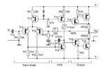
Lately I'm reading a book on (audio) amplifier design. I have some questions about the Miller capacitor in the attached schematic.
From this audio book I read:

"The global (overall) feedback factor at low frequencies is sufficient to linearise the VAS, while at high frequencies shunt negative feedback through Cdom conveniently takes over VAS-linearisation while the overall feedback factor is falling."

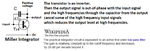
I see how the global feedback works, but not the local feedback by the Miller capacitance. Where does the feedback action take place and how is the VAS (Voltage Amplification Stage) linearised?

Thanks in advance.
 

Attachments

  • 3stage.png
    3stage.png
    33.5 KB · Views: 152

High frequency phase shifts in an amplifier or opamp cause it to oscillate at a high frequency when negative feedback is added because then the high frequencies produce positive feedback. So the compensation capacitor is added at the VAS stage to cut gain at high frequencies so that the gain is less than one at frequencies where it would oscillate. When the gain is less than one then it cannot oscillate.

Global negative feedback linearizes and reduces distortion. If you look at the distortion vs frequency of any audio power amplifier or opamp then you will see the distortion rise at high frequencies.

Don't you see that a capacitor from the collector to the base of the VAS common emitter transistor cuts its gain at high frequencies because the collector signal is 180 degrees out of phase with the base signal?

Here is a graph of the open-loop voltage gain of a TL071 opamp that begins cutting high frequencies above about 20Hz. But the next graph shows that its distortion over the entire range of audio frequencies up to 20kHz is extremely low then rises above 20kHz.
 

Attachments

  • amplifier compensation.png
    amplifier compensation.png
    48.7 KB · Views: 136
  • Like
Reactions: Farad22

    V

    Points: 2
    Helpful Answer Positive Rating

    Farad22

    Points: 2
    Helpful Answer Positive Rating
Don't you see that a capacitor from the collector to the base of the VAS common emitter transistor cuts its gain at high frequencies because the collector signal is 180 degrees out of phase with the base signal?

The way I see it, is that as frequency goes up more of the signal current from the input stage flows into the compensation capacitor and that the current flowing into the base decreases with rising frequency. Is this correct? What I don't see is how it makes the VAS more linear.
 

The compensation capacitor uses some high frequency signal at the collector of the transistor to cancel some high frequency signal at its base.
The compensation capacitor has nothing to do with making linearity. It simply cuts high frequencies so that the amplifier does not oscillate when negative feedback around the entire amplifier is applied.

It is the negative feedback that cancels almost all low frequency distortion caused by nonlinearity. The amplifier has a voltage gain of maybe 100,000 times (some opamps have a gain in the millions) without negative feedback. If a voltage gain of only 100 times is wanted then negative feedback is applied and distortion is reduced 100,000/100= 1000 times. So if distortion without negative feedback is 20% then with the negative feedback it is only 0.02% at low frequencies.
 
The compensation capacitor uses some high frequency signal at the collector of the transistor to cancel some high frequency signal at its base.

Could you expose on this? I don't see where the feedback action takes place. In which place in the schematic is a voltage/current opposed?
 

I do not know why you do not understand the actions of a Miller Integrator. It cuts high frequencies.
 

Attachments

  • Miller integrator.png
    Miller integrator.png
    23.8 KB · Views: 120

Status
Not open for further replies.

Part and Inventory Search

Welcome to EDABoard.com

Sponsor

Back
Top