Continue to Site

Welcome to EDAboard.com

Welcome to our site! EDAboard.com is an international Electronics Discussion Forum focused on EDA software, circuits, schematics, books, theory, papers, asic, pld, 8051, DSP, Network, RF, Analog Design, PCB, Service Manuals... and a whole lot more! To participate you need to register. Registration is free. Click here to register now.

Fast step signal generator.

Status
Not open for further replies.

eslavko

Junior Member level 2
Joined
Jan 22, 2010
Messages
22
Helped
0
Reputation
0
Reaction score
0
Trophy points
1,281
Location
Slovenia, EU.
Activity points
1,479
Hello....

Long time ago I build TDR. It has 47AC14 as pulse generator, but now I want to improve it. AC14 is just little to slow and has excsive ringing. I do search a lot and found that SRD is way to go. (Avalanche generator is other direction as I want step and not pulse) HC14 has no ringing but is slower too.

So SRD diode is not easy to get, and seems expensive to. Then I found one paper at https://www.adv-radio-sci.net/2/7/2004/ars-2-7-2004.pdf
that use BJT instead SRD for same functionality. But sadly there are no schematic how to connect transistor and I don't find solution yet. Basically I ned to put transistor into saturation and then reverse bias it. How to do with one signal?!?

Thanks
 

Hi,

what about using a fast analog switch?
Then you may adjust both levels: high and low.. with simple DC generation.

Are you sure the ringing is caused by the AC14? I rather think it is caused by: stray inductance, wiring, pcb layout, cable, impedance mismatch...

Klaus
 

SRD would be the right way for a 10 to 100 ps rise time range. I assume, you are not needing this high speed?

An avalanche transistor does primarly a fast falling (or rising) edge, in so far it's well suited for step generation, or short square wave with an additional delay line.
But signal quality isn't as perfect as with a CMOS gate or switch.

What's your rise-/falltime and voltage requirement?
 

Hello...

Actually I need fast rise from 0 to 5V (0 to 4V is OK) with step under 1nS. Then I need steady 5V aprox 30uS long. The fall edge is not important. Then there is recovery time aprox 60uS long.

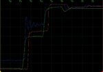
Here is attached image of TDR output. AC-HC-FET-Short.jpg
Blue line is with 74AC14, Red line is with 74HC14 and green line is just BS170 as inverter.
 

CMOS gates are fine for 1 ns rise time. I achieved 650 ps with matched 50 ohm output using single gate drivers. I should mention that the circuit had been primarly designed for analog signal quality instead of fastest rise time.

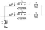
Output circuit
Output stage.jpg

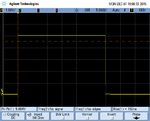
Pulse
Pulse 5V 30 us.png

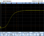
Risetime open circuit (filtered by oscilloscope input capacitance)
Risetime 5V open circuit.png

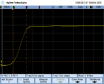
Risetime into 50 ohm
Risetime 50 ohm.png
 
...I tried avalanche generator but pulse is to short. I need aprox 30uS long pulse with fast rise time (under 1ns) and don't care :razz: fall time.
I was able to extend pulse to 5uS but then got into trouble as there is long charge time for capacitor. And other problem is that triggering avalanche (injecting signal to base) is not precise and produce big jitter.
Drive signal is pin from AVR microcontroller.

- - - Updated - - -

FvM that seems good. But my signal from AVR is little slow and as I see there are no schmidt trigger in gate.
 

Hi,

it seems you are switching a FET.. The scope picture shows a typical miller plateau.

**
did you consider to use LVC logic? Or fairchild NC7SZ logic?

The AC14 is a schmitt trigger, usually non_schmitt_trigger devices are faster.
Paralleling of some devices could shorten the miller plateau.

Did you consider to use non_logic, but real high speed FET drivers?

With CMOS switches i thought of something like TS5A23160. But be carefull, they are make_before_break! They are fast and can drive a lot of current.

Klaus

Added:
I again was too slow in answering. FvM had similar ideas....
 

FvM that seems good. But my signal from AVR is little slow and as I see there are no schmidt trigger in gate.
 

These are double buffered gates, I'm feeding it with a LMC555 in my test generator with is neither particularly fast. I won't expect increased risetime with standard GPIO output signals, but to be serious, I never checked.
 

I should explain what is in picture. That is signal response from aprox 5m of twisted pair cable. (I want to make better Time Domain Reflectometer)
So the 1st rise is actual step from generator and second one is reflection as cable is not terminated. I do tried with HC, AC, LVC logic but wasn't avare of NC7SZ until now. I use schmidt trigger as I think slew rate from AVR is to slow and weak for triggering 5x HC/AC/LVC gates.
And signal delay is no concern (as long as is coherent) but the slew rate is.
 

If generator risetime turns out to be problem, add another driver in front of the output stage.

NC7SZ series isn't very different from 74AHC single gate devices. You are however creating a problem when using SO or even DIL multi gate devices with a single gnd terminal. GND and VCC wiring is essential for good signal quality, also very good supply bypassing.

Regarding your TDR screenshots, I fear without additional info it's impossible to see where the ringing comes from. I found my test generator (which had been designed for evaluation of test equipment 10 years ago) well suited for cable TV TDR measurements, too.

Connecting differential lines would require some kind of balun or at least a common mode filter.
 

I have two prototipes. One with THT dil and other SMD. One layer of PCB is ground other vcc and signals. I have decoupled with ceramic and tantalum on each chip. I know that socket is no god but for experimentig I have it. And just replacing HC with AC cause exesive ringing. I assume that AC is cause as all other devices doesnt ring. But I want sharper step response as with that anomaly in line is visible sharper.
 

Hi,

I never build such a reflectometer....But instead of driving with low impedance (wich means low voltage drop) I'd use a defined ohmic resistor. Maybe in the range of 50..120 Ohms.
With it I expect a more defined voltage step. I expect to be able to measure the wave impedance with the height (voltage) of the first plateau (and the source resistance). And the length with the timing.
But as said, I really don't know.

Klaus
 

There are over 75 families of logic still active with variations of several parameters.
The fastest rise times will always be current mode logic. the best in class CML like the ancestors ECL can achieve very low rise times. The fastest I have seen is ~10 ps with 50 Ohm terminations.

The differential versions of current switches are LVDS, HSTL, CML with 75 fento-second (fs) jitter RMS on devices such as SY89327L , CMOS to CML translator.

CMOS has evolved over 4 decades from 300 Ohms need to operate at high voltage for speed to 50 Ohms @ 5V to <25 Ohms that must operate at low voltage <+3.3V for shootthru transition power reasons.

If using ALC or LVC or ALVC2 or NC7SZ or LCX keep in mind the output impedance at your operating Vcc and temp will need to have a small series R to match the 50 Ohms ( perhaps <=25 Ohms. )

ALthough I would CML.
 

Like others, I assume that the observed ringing is a layout and (to a lesser extent) package parasitics problem. You should expect similar problems with other fast drivers, too.

You didn't yet show how you hooked up generator and oscilloscope to the cable.
 

As I'm not sure if PCB layout is the problem I just soldered one 74AC14 like dead bug on piece of blank PCB. It's DIL but I cut the legs so it's onli aprox 1mm long and soldered to ground plane. Vcc is decoupled with 100nF ceramic and 47uF Tantalum. Added one more cap and resistor to make oscillator with one gate and that drive other gate. All other inputs are grounded. Then I hook 1:10 scope probe and check directly on pin. There are ringing. Actually the more ringing. Then I solder 100 Ohm resistor from pin to ground plane and measure again. The ringing is near same. With 50 Ohm resistor is barely visible better. So I assume that AC family rings. (The ringing is oscillation little under 300MHz).
I do never do anything with ECL but as I know that is low signal design. I need at least 3V difference signal.
As I see all logic family listed here (except ECL) are declared slew rate over 1nS but I want under 1nS.
 

Hi,

no comment about the analog switches? No good idea?

What about high speed low side fet drivers like: UCC27516
I know they specify a lot more ns rise time, but see the huge load of 1.8nF.
I´m sure there are faster drivers.

Klaus
 

I do check analog switches. But seems to be to slow or underpowered. As I need actual line driver for 50/100/120 Ohm cables and up to 1000m long I think all logic ates and similar seems to be out of question. Basic I=U/R give me that driver need to put at least 100mA, but cable act as capacitor too. So over 0.1A is needed.
I do look into that FET gate drivers but are listed at slew rate in range of few ns. Maybe I should test that as maybe is switch a lot faster with smaller load. God idea with that. sadly doesn't have any of them at home. I'm more and more biased to do some discrete stuff to drive that line. Just need good schematic.

- - - Updated - - -

I do found MCP1407 driver and tested. Result was clean step with (slow) risetime of 13nS. Unusable for that application. I do check response with 1nF capacitor connected and risetime barely change. So 74AC14 is winner with 2.1nS and bad ringing, and HC14 or BS170 as inverter second with 3.3nS without ringing. So how to go under 1nS? Inverter with discrete components?
 

So to got back on topic. Does someone understand the document in link on the 1st post?!?
Figure 3 on have just what I want. So what I get the circuit is common emitter. (and described in text too).
As there are no schematic I tried to reverse engineer the pcb on Figure 10.
I assume that bottom plane is ground. So the "transistor circuit" seems to have:
Two emitters grounded (bot left and top right pin)
Base (top left) is probably driven with capacitor (amber element) and biased with two resistors decoupled and feed with unknown element (green one) The output (collector) seems to be capacitor coupled to output diode, and again biased with unknown component (green one). There seems to be decoupling too and fedded with left bottom red wire. So How on the world they achieve required condition?
Its stated that transistor should be saturated (Emiter < Base > Collector) and then reverse biased (Emiter > Base > Collector) Any idea? I really like to try this animal.
 

Status
Not open for further replies.

Part and Inventory Search

Welcome to EDABoard.com

Sponsor

Back
Top