Continue to Site

Welcome to EDAboard.com

Welcome to our site! EDAboard.com is an international Electronics Discussion Forum focused on EDA software, circuits, schematics, books, theory, papers, asic, pld, 8051, DSP, Network, RF, Analog Design, PCB, Service Manuals... and a whole lot more! To participate you need to register. Registration is free. Click here to register now.

Extending the TX of commercial handheld transceiver

Status
Not open for further replies.

neazoi

Advanced Member level 6
Joined
Jan 5, 2008
Messages
4,119
Helped
13
Reputation
26
Reaction score
15
Trophy points
1,318
Location
Greece
Activity points
36,918
Hi I have a commercial uhf fm transceiver that can operate TX/RX at 432MHz. The transceiver has a dual receiver and the RX can operate up to 1300MHz FM, covering the 23cm amateur band (1296MHz).
I am thinking to extend the TX range of it, so that I can TX on 23cm as well.
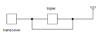
The simplest solution I am thinking of is a TX tripler (sinse it requires no DC power) in series with the TX output and the antenna.

A simple diode tripler can be used for the purpose https://www.qsl.net/va3iul/Homebrew...as/432MHz_1296MHz_Varactor_Tripler_WA6UAM.gif
The FM deviation will be set to minimum on 432MHz to cope with the tripler.
Instead of building and tuning the output filter, I am thinking of using the mini circuits CBP-1260C+ which can tolerate an input of 0.5W max.

The transceiver mutes the RX when transmitting. I basically transmit on 432MHz (which is multiplied to 1296MHz), whereas I monitor the 1296MHz. My problem is, how do I do the switching from the tripler to the transceiver and antenna? Is it enough to do it like in the sckematic, since the RX is disabled during transmit? I think I must include a diode somewhere, so that the 432MHz tx does does not bypass the tripler.
Any other power-free ideas?
 

Attachments

  • Untitled.png
    Untitled.png
    1.8 KB · Views: 71

I would up mix rather than use a tripler. For one thing, they only work on FM and as you have noted, you need to change the modulation index to restrict the bandwidth. This can have consequences with audio ALC and compression if the transceiver has those features. Also bear in mind that PLL and other circuit noise will still be 3 times greater, even if you turn the audio level down.

You will find a tripler is very inefficient, probably less than 10% so your output power will be in the tens of mW range. My own 23cm transmitter just uses a varicap tuned VCO followed by two stages of amplification then a Mitsubishi 'brick' module to produce around 20W output. It isn't PLL stabilized but I do leave the VCO running all the time and just kill the power to the amplifer stages when receiving.

Brian.
 
  • Like
Reactions: neazoi

    neazoi

    Points: 2
    Helpful Answer Positive Rating
I would up mix rather than use a tripler. For one thing, they only work on FM and as you have noted, you need to change the modulation index to restrict the bandwidth. This can have consequences with audio ALC and compression if the transceiver has those features. Also bear in mind that PLL and other circuit noise will still be 3 times greater, even if you turn the audio level down.

You will find a tripler is very inefficient, probably less than 10% so your output power will be in the tens of mW range. My own 23cm transmitter just uses a varicap tuned VCO followed by two stages of amplification then a Mitsubishi 'brick' module to produce around 20W output. It isn't PLL stabilized but I do leave the VCO running all the time and just kill the power to the amplifer stages when receiving.

Brian.

The ONLY good part about the tripler, is that it can be made passive, so no dc power is required.
In a handheld transceiver size and DC power does matter. I was thinking of including the tripler block just below the rubber antenna, between the transceiver and the antenna. It will be made as a series plug in.

It it needs to be active, it has to operate in low DC voltage and the batteries must exist as a part of the antenna, so obviously not much series AA/AAA batteries can be used.

PS I desperately need a 1.2v to 9v or 12v inverter IC, to investigate if this can be done with a single AA/AAA in place. If you have any ideas please let me know.
 

I would up mix rather than use a tripler. For one thing, they only work on FM and as you have noted, you need to change the modulation index to restrict the bandwidth. This can have consequences with audio ALC and compression if the transceiver has those features. Also bear in mind that PLL and other circuit noise will still be 3 times greater, even if you turn the audio level down.

its a FM only transceiver only anyway so irrelevant. yes modulation index and level is increased ... many transceivers have to ability to change deviation from front panel controls

You will find a tripler is very inefficient, probably less than 10% so your output power will be in the tens of mW range. My own 23cm transmitter just uses a varicap tuned VCO followed by two stages of amplification then a Mitsubishi 'brick' module to produce around 20W output. It isn't PLL stabilized but I do leave the VCO running all the time and just kill the power to the amplifer stages when receiving.
Brian.

triplers ... in my wide use of them, are quite efficient easy to get min of 50% and up to 60% I have easily been able to produce a clean 5 - 6 W out on 23cm of one when feeding 10W in on 70cm ( as from a typical mobile transceiver)
And even if you wanted to be REALLY conservative, you could still get 2 to 4W out on 23cm, which is a very respectable power level on that freq
My commercial DJG-7, 23cm handheld 1W, can do 90km LOS

The old classic varactor diode ( getting harder to find these days) was the BAY96. it can handle up to around 15W in on 432MHz


Dave
 
  • Like
Reactions: neazoi

    neazoi

    Points: 2
    Helpful Answer Positive Rating
PS I desperately need a 1.2v to 9v or 12v inverter IC, to investigate if this can be done with a single AA/AAA in place. If you have any ideas please let me know.

Here's a thread which discusses a boost converter switched by two transistors. You'll need to adjust values to suit.

https://www.edaboard.com/threads/283209/
 
  • Like
Reactions: neazoi

    neazoi

    Points: 2
    Helpful Answer Positive Rating
The old classic varactor diode ( getting harder to find these days) was the BAY96. it can handle up to around 15W in on 432MHz
Dave
I have one and it is indeed hard to find. However the max input power in my case would be around 0.5-1w. So other smalled step recovery diodes could be used.

- - - Updated - - -

Here's a thread which discusses a boost converter switched by two transistors. You'll need to adjust values to suit.

https://www.edaboard.com/threads/283209/

This is a doubler. Obviously it is not intended for the purpose as the voltage would be too low. I have not seen a single stage 1.2v to 12v converter anywhere...
 

I have one and it is indeed hard to find. However the max input power in my case would be around 0.5-1w. So other smalled step recovery diodes could be used.

...

yeah, I just reread the title ... I missed the handheld part thought it was a mobile transceiver ... so with 1W on 432 you might get 100 - 200 mW ... the varactors are definitely more efficient with higher power levels

what make and model HH is it ? most these days are capable of 2 - 5W


Dave
 
  • Like
Reactions: neazoi

    neazoi

    Points: 2
    Helpful Answer Positive Rating
Originally Posted by BradtheRad
Here's a thread which discusses a boost converter switched by two transistors. You'll need to adjust values to suit.

https://www.edaboard.com/threads/283209/

This is a doubler. Obviously it is not intended for the purpose as the voltage would be too low. I have not seen a single stage 1.2v to 12v converter anywhere...

Today I experimented with this boost converter. A real circuit using real components. From a 1.2V cell, it lit up a bright white led at 3.6V. With the load a few mA it went higher than 8V.


It is tricky to get consistent switching of the transistors, to continue to oscillate. The bias adjustment must be correct. There is a certain range of pot value, and a certain range of positions, which will result in reliable operation.
 
  • Like
Reactions: neazoi

    neazoi

    Points: 2
    Helpful Answer Positive Rating
yeah, I just reread the title ... I missed the handheld part thought it was a mobile transceiver ... so with 1W on 432 you might get 100 - 200 mW ... the varactors are definitely more efficient with higher power levels

what make and model HH is it ? most these days are capable of 2 - 5W
Dave
It is the Kenwood TH-F7E. I definitely not want to run it on 5W on it's antenna, imagine on the unmatched varactor diode. It has to operate at lower powers for transmitter safety.
100mW on 1296MHz is not too bad for local comms. However, one has to consider the antenna efficiency as well.
 

Status
Not open for further replies.

Part and Inventory Search

Welcome to EDABoard.com

Sponsor

Back
Top