Irina F
Newbie level 4
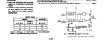
For my temperature control circuit, the first part delivers a PWM signal at 5V, which then needs to be shifted to 12V in order to command a power driver and then a TEC. I am using therefore a CD40109B level shifter, but I am not really sure how to connect the pins. Of course, the following connections need to be made:
Vcc (pin 1)-> 5V
Vss (pin 8)-> GND
Vdd (pin 16)-> 12V
A (pin 3)-> PWM input signal
And now the question is: where to I collect the output signal shifted to 12V? On Enable A (pin 2) or E (pin 4)? And do I need to connect any other pins to 5V for instance?
Thank you in advance!
Vcc (pin 1)-> 5V
Vss (pin 8)-> GND
Vdd (pin 16)-> 12V
A (pin 3)-> PWM input signal
And now the question is: where to I collect the output signal shifted to 12V? On Enable A (pin 2) or E (pin 4)? And do I need to connect any other pins to 5V for instance?
Thank you in advance!