Continue to Site

Welcome to EDAboard.com

Welcome to our site! EDAboard.com is an international Electronics Discussion Forum focused on EDA software, circuits, schematics, books, theory, papers, asic, pld, 8051, DSP, Network, RF, Analog Design, PCB, Service Manuals... and a whole lot more! To participate you need to register. Registration is free. Click here to register now.

Explanation of de-embedding in EM simulation

Status
Not open for further replies.

stefanpo

Newbie level 4
Joined
May 14, 2012
Messages
5
Helped
1
Reputation
2
Reaction score
1
Trophy points
1,283
Activity points
1,337
Hello all, I am confused with the concept of de-embedding in EM simulation and would be very happy if someone can help me out.

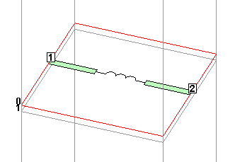
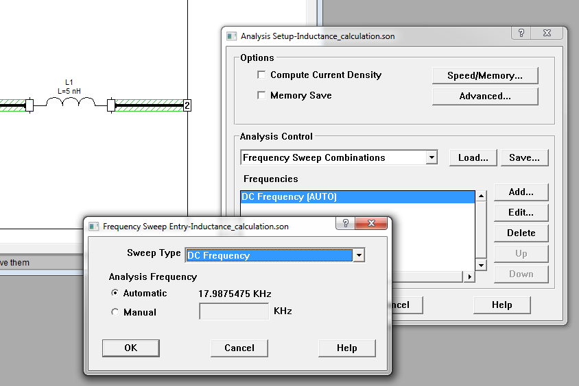
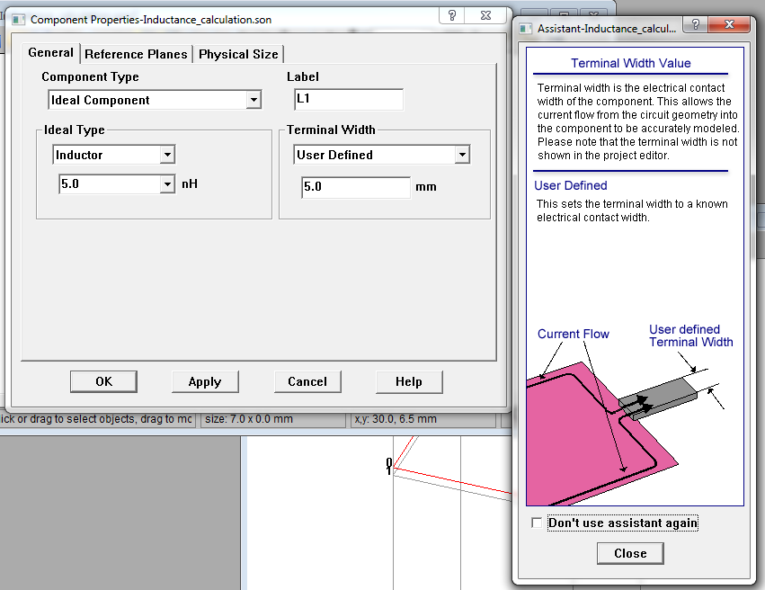
As a beginner in EM simulation, I understood that de-embedding helps to eliminate the influence of surrounding components (e.g. feed lines) when modelling the true frequency response of the device under test. For example, if I have an ideal inductor connected with transmission lines in two ends, the effect from the transmission lines on the inductance of the inductor will be cancelled out if I set the reference planes at the ports of the ideal inductor. Therefore if the inductor has inductance 5 nH, then one would expect the simulated results would be 5 nH, at least in low frequency.

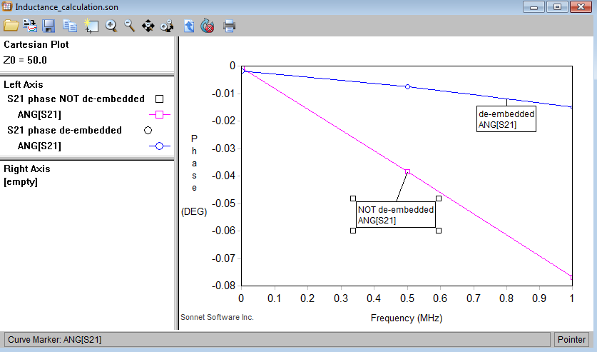
When I tried to realized the above concept in Sonnet, I found a different story. The simulated inductance deviates from the ideal values. Moreover, when I change the width of the transmission line, the inductance also changes. This means the transmission lines still have influence on the simulation even I set the reference plane of de-embedding at the two ports of the ideal inductor.

Any help in Sonnet or pointing out my misunderstanding would be much much appreciated :)

See attachment for the results in Sonnet.

Stefan

Picture1.jpgView attachment Inductance_calculation.rar
 
Last edited:

Re: De-embedding concept

Something is wrong here. After de-embedding you should get 5nH, if the requirements for port de-embedding are fulfilled. One requirement is that the feedlines behave like single moded transmission lines.

Either the feedlines lines are violating these assumptions (far away from any ground) or something else is wrong. One possible problem at low frequency is numerical precision, if the cell size is smaller that 1E-6 wavelength or so. The Sonnet method does have a lower frequency limit, and the so called "DC" point in the "Frequency Sweep Combinations" is really a very low (but still valid) frequency where the model behaves DC-like.

Can you ZIP and upload your *.son model file?
 

Re: De-embedding concept

Thanks Volker for your reply. I have now attached the sonnet file in my original post. Really looking forward to hearing comments from your side : )
 
Re: De-embedding concept

Stefan,

there are multiple problems with your testcase setup.
Most of that is from using a microwave simulator at very low (kHz) frequency, which causes precision problem.

The biggest, fundamental issue is that you try to extract a really small inductance at very low frequency, using S-parameters. The inductance2 equation evaluates the series path, which is very close to ideal for 5nH at low frequency (1kHz to 1MHz). Calculating an inductance from that very small difference to ideal is sensitive to precision of the EM data. The de-embedding does remove the feedlines, but there is a residual phase error of 0.002 degree at low frequency, which results in a large equivalent inductance at this low frequency.


Second, there is no clean ground below the lines, which reduces the accuracy of de-embedding. Remember that de-embedding is based on single moded transmission lines.

18_1342003317.png


Finally, the analyzed frequency down to 1kHz are too low and cause precision errors in EM (singular matrix). The Sonnet Method of Moments is based on differences in current/voltage between the cells, and does not work at 0 Hz. It does need some difference between subsections, so that subsections should not be smaller than 1E-6 * wavelength.

As I indicated above, you can get "DC-like" data if you select the DC point in the "Frequency Sweep Combinations". This uses a very low frequency that should still be safe to use. I use that DC point for RFIC work where I need wideband results from DC to 100GHz or so, and that works great.


In conclusion, you will get much better results at RF/microwave frequencies, where Sonnet works as designed, and with a proper ground under the de-embedded feedlines.
 
Last edited:

Re: De-embedding concept

Danke Volker!

Besides your points, I also found out that in my simulation setting, I set the Terminal Width of the inductor incorrectly. Once I set it as "Feedline Width", the simulated inductance is exactly 5 nH even in high frequency.

I guess the interface between the feedline and the ideal component play an important role here even in the de-embedding environment. One has to make sure the width of the feedline and the width of the device under test is the same, isn't it?

Picture2.jpg
 

Re: De-embedding concept

I guess the interface between the feedline and the ideal component play an important role here even in the de-embedding environment. One has to make sure the width of the feedline and the width of the device under test is the same, isn't it?

Yes, the step in width between feedline and component will cause some inductance. In circuit simulators, we have an MSTEP element to model such change in width.

The change in width between feedline and component is also included in the Sonnet model, if you set a component pad width that is different from the feedline width. The context sensitive help give some instructions.


I have attached two more slides from the Sonnet training on ports/components:


Status
Not open for further replies.

Part and Inventory Search

Welcome to EDABoard.com

Sponsor

Back
Top