Continue to Site

Welcome to EDAboard.com

Welcome to our site! EDAboard.com is an international Electronics Discussion Forum focused on EDA software, circuits, schematics, books, theory, papers, asic, pld, 8051, DSP, Network, RF, Analog Design, PCB, Service Manuals... and a whole lot more! To participate you need to register. Registration is free. Click here to register now.

Explain to me the working of op-amp in this low pass filter

Status
Not open for further replies.

zarric

Junior Member level 3
Joined
Nov 13, 2007
Messages
31
Helped
0
Reputation
0
Reaction score
0
Trophy points
1,286
Activity points
1,487
about filter design

For the below low pass filter:


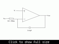
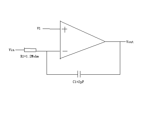
OP is basic two stage
two points i wanted to know:
1. C1 connected Vout and negative input , how to know it's stability and how to compensate.
2. the OP has two pole about 100khz, but when i put a ac source at vin , the gain and phase at Vout shows that only a input pole about 5hz, then no any pole or zero unit 10Mhz. why for this.

thanks
 

Re: about filter design

Hi,
See the topic:

Firstly, you should insure the stability of the opamp. If the opamp has two poles at 100kHz it might be unstable. You should compensate it. The miller compensation or cascode compensation could be used (for more information on how to apply the methods, you can see the Gray book or Razavi book).
 

Re: about filter design

thanks.

the feedback ratio may larger than 1 , so whether this loop is always stability , and how to simulater and know that is stability.
 

Status
Not open for further replies.

Part and Inventory Search

Welcome to EDABoard.com

Sponsor

Back
Top