tahir4awan
Full Member level 4
Hi can anyone explain me this simple code
============================================================
void main(){
ANSEL = 0; // Configure AN pins as digital I/O
ANSELH = 0;
PORTB = 0;
TRISB = 0; // Configure PORTB as output
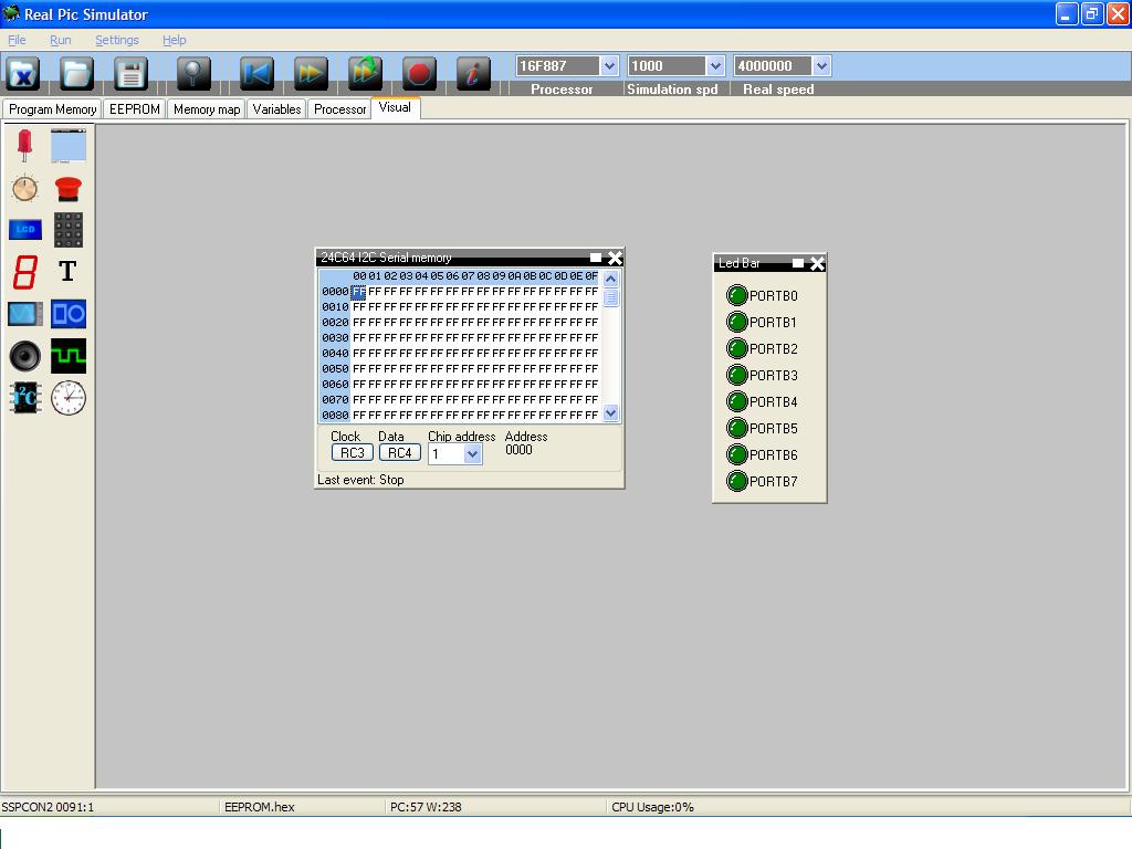
I2C1_Init(100000); // initialize I2C communication
I2C1_Start(); // issue I2C start signal
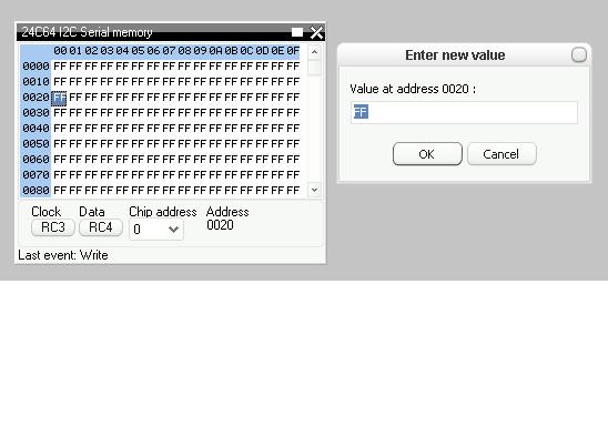
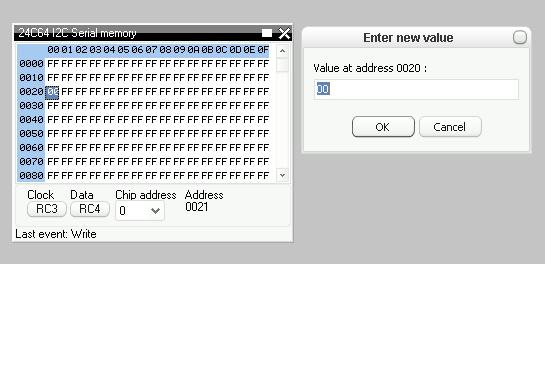
I2C1_Wr(0xA2); // send byte via I2C (device address + W)
I2C1_Wr(2); // send byte (address of EEPROM location)
I2C1_Wr(0xAA); // send data (data to be written)
I2C1_Stop(); // issue I2C stop signal
Delay_100ms();
I2C1_Start(); // issue I2C start signal
I2C1_Wr(0xA2); // send byte via I2C (device address + W)
I2C1_Wr(2); // send byte (data address)
I2C1_Repeated_Start(); // issue I2C signal repeated start
I2C1_Wr(0xA3); // send byte (device address + R)
PORTB = I2C1_Rd(0u); // Read the data (NO acknowledge)
I2C1_Stop(); // issue I2C stop signal
}
===========================================================
============================================================
void main(){
ANSEL = 0; // Configure AN pins as digital I/O
ANSELH = 0;
PORTB = 0;
TRISB = 0; // Configure PORTB as output
I2C1_Init(100000); // initialize I2C communication
I2C1_Start(); // issue I2C start signal
I2C1_Wr(0xA2); // send byte via I2C (device address + W)
I2C1_Wr(2); // send byte (address of EEPROM location)
I2C1_Wr(0xAA); // send data (data to be written)
I2C1_Stop(); // issue I2C stop signal
Delay_100ms();
I2C1_Start(); // issue I2C start signal
I2C1_Wr(0xA2); // send byte via I2C (device address + W)
I2C1_Wr(2); // send byte (data address)
I2C1_Repeated_Start(); // issue I2C signal repeated start
I2C1_Wr(0xA3); // send byte (device address + R)
PORTB = I2C1_Rd(0u); // Read the data (NO acknowledge)
I2C1_Stop(); // issue I2C stop signal
}
===========================================================