Continue to Site

Welcome to EDAboard.com

Welcome to our site! EDAboard.com is an international Electronics Discussion Forum focused on EDA software, circuits, schematics, books, theory, papers, asic, pld, 8051, DSP, Network, RF, Analog Design, PCB, Service Manuals... and a whole lot more! To participate you need to register. Registration is free. Click here to register now.

Experts please test and improve this shunt mode solar charger circuit

Status
Not open for further replies.

samshoppy

Newbie level 3
Joined
May 26, 2012
Messages
3
Helped
1
Reputation
2
Reaction score
1
Trophy points
1,283
Activity points
1,300
I have modified basic lm339 comparator circuit to work as shunt mode solar charger.

Pin 1 works as low voltage cutout. When voltage drops, led goes off and tip127 turns off.

Pin 14 works as overcharge cutout. Normally led remains on & tip127 also. Current flows to battery through tip127. when voltage goes high led goes off and tip 127 stops charging. Diodes at Emitter protects direct flow of current in both sides. 100k is used for hysteresis.

Please add auto switch on circuit when current from solar panel stops flowing.
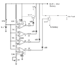
lm339 solar charger.png
 

You can open the PV source with a High Side switch instead of using the diodes.
Alternatively you can shunt it to a dummy load such as another battery or a water pump or 4 Cree LEDs that can handle the expected power at 14.5~14.6V.

Also , I think Solar cells have a characteristic impedance as leaky current sources. We know that maximum Power transfer occurs when the source and load impedances are matched.

Here they are not.

I suggest you verify what voltage is optimum for power transfer on your PV array at a range of solar power inputs. Then consider what the optimum PV voltage should be vs Current. THis impedance curve is what you ought to match in your charger. In some cases a high PV array rated at 19~24V is not efficiently transferred dumping into a 12V battery. If your PV cells are flat power transfer over the wide range of voltage, no sweat. If not, you can improve the design with an impedance transformer. There are two kinds for DC. With a low ESR Cap across the PV array and a low ESR battery at a lower voltage , and a suitable inductor between a PWM switch and the two low ESR ends you can match impedances and regulate the voltage on the PV by adjusting the duty cycle in a closed loop.The other method is a simple PWM between two ends where the impedance is scaled up by the ratio of on/cycle time. So Reff= ESR/duty cycle. Note R effective =ESR of circuit at 100% and is open circuit at 0%. and twice the impedance @ 50%.. the pulses also help reduce sulphation crystaline build up on the plates, which raises battery ESR and lowers specific gravity.,

If you want to display transfer power , you need a multiplier chip to multiply the current * battery voltage or use an old automotive ampere gauge as the cell voltage is fairly constant between 12.5 and 14.5V
 

Status
Not open for further replies.

Similar threads

Part and Inventory Search

Welcome to EDABoard.com

Sponsor

Back
Top