Continue to Site

Welcome to EDAboard.com

Welcome to our site! EDAboard.com is an international Electronics Discussion Forum focused on EDA software, circuits, schematics, books, theory, papers, asic, pld, 8051, DSP, Network, RF, Analog Design, PCB, Service Manuals... and a whole lot more! To participate you need to register. Registration is free. Click here to register now.

Example for DC-offset correction with a LPF

Status
Not open for further replies.

milvapp

Member level 5
Joined
Apr 17, 2010
Messages
88
Helped
3
Reputation
6
Reaction score
2
Trophy points
1,288
Location
chania greece
Activity points
1,882
Hi all,

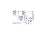
does anyone know of a good example showing how a LPF
cancels DC-offset in feedback path(active negative feedback)?

I know that the LPF senses the DC-offset which is in turn
substracted from the signal,but i haven't understood it well.
So a good example would help me.

Thank you in advance.
 

It's not exactly what i was looking for but thank you for your interest.
 

That is a simple example of using a low pass filter to correct for the DC offset, although I guess it is more of an integrator. What exactly were you looking for?

Keith.
 
I was meaning something like the one depicted at the attachment.
What I saying is that I do know how to design it,I dont know how it works though.
I am looking for an explanation.The LPF has a cutoff frequency of 500 KHz.
a)Why is that?Does the Dc-offset appear only in low frequencies given that the
multistage Vgas work at 2.2 GHz.
I know that the LPF's function is to sense the DC magnitude and then add/subtract it
through the feedback amplifier,but I havent fully understood it.
b)For example,let's say that VGA4out(+)= 10mV and VGA4out(-)= 0mV for
VGA4in(+)= VGA4in(-)=0 mV.Then we have DC-offset at VGA4out(+) right?
So the LPF senses the offset (somehow?) and then through the feedback amplifier
adds the offset (10mV) to VGA4in(-).In that way the offset is subtracted.Correct me if I am wrong
c)The fact that the resistor at the filter is a cascaded PMOS(working in subthreshold region)resistor
does the varying incoming DC magnitude affect it?I mean does it make it an adaptive filter?Or will it work on the same gain whether the VGA4out(+)= 10mV or VGA4out(+)= 500mV(considering we have the same frequency)

I hope I became more specific.
 

Attachments

  • dc offset correction.jpg
    dc offset correction.jpg
    18.5 KB · Views: 236
Last edited:

Do you have a link or reference where you got the circuit from? The reason I ask is because the feedback amplifier looks like it produces a current output and VGA3 presumably doesn't have a low impedance voltage output otherwise the circuit wouldn't work. An explanation of the circuit requires some knowledge of the internals of the amplifier blocks in this case.

While you talk about DC offsets, the fact that it uses a low pass filter means it will track changing offsets. As the LPF in your example is 500kHz then it will track fairly rapid changes in the offset. You would normally want to keep the LPF well away from the signal of interest otherwise the DC correction will try to remove the signal as well. The signal in your case is 2.2GHz - well away from the 500kHz.

So, in a simpler example, like the one I gave, a filtered, inverted version of the output signal is added to the input signal to cancel out the offset. The same thing is happening with your circuit, but it is more complex because it is fully differential and a current output error amplifier is used.

The output of a low pass filter when fed with a very high frequency (well above its cutoff frequency) is the "average" of the input voltage.

I am not sure if I have helped much.

Keith.
 
Do you have a link or reference where you got the circuit from? The reason I ask is because the feedback amplifier looks like it produces a current output and VGA3 presumably doesn't have a low impedance voltage output otherwise the circuit wouldn't work. An explanation of the circuit requires some knowledge of the internals of the amplifier blocks in this case.

This is the link. bwrc.eecs.berkeley.edu/publications/2008/Ali/yanjie.pdf
Please make any comment if you think it may help.

You have helped me pretty much so far and i have to thank you for your insight.
 

DC cannot pass through a high pass filter so if you put one in the signal path it will remove the DC offset. It can only remove DC before the filter so unless the filter is the last thing in the signal chain there could still be some DC left due to amplifier offsets.

Keith
 
.

While you talk about DC offsets, the fact that it uses a low pass filter means it will track changing offsets. As the LPF in your example is 500kHz then it will track fairly rapid changes in the offset. You would normally want to keep the LPF well away from the signal of interest otherwise the DC correction will try to remove the signal as well. The signal in your case is 2.2GHz - well away from the 500kHz.

Keith.

Hi Keith ,it's almost 2 years after I made the post but I would like to clarify a thing for for educational purposes.Based on the example above,I have not understood how an LPF filter could degrade the original signal..Does it have to do with poles and zeros?I am quite novice to this area and I would like you to explain to me if you can.The signal will have a standard amplitude no matter the frequency, right?So in the previous example is like degrading the signal in a percent of 0.5/2.2 *10^-3 ??

Thank you in advance,
Vasilis
 

It is probably best illustrated by changing the sine wave to a square wave in the example I gave earlier. As you can see the square wave is quite distorted due to the offset correction. This is probably a rather extreme example but shows what happens when the time constant of the offset correction circuit is not far enough from the actual signals in use. With a sine input the only effect would be to alter the amplitude but with any other shape waveform you have frequencies other than the fundamental to worry about. If you alter the phase or amplitude of some of the components then the shape of the waveform will change.

Keith.
 

Attachments

  • EDA 122 LPF offset correction.pdf
    41 KB · Views: 103
Status
Not open for further replies.

Part and Inventory Search

Welcome to EDABoard.com

Sponsor

Back
Top