Continue to Site

Welcome to EDAboard.com

Welcome to our site! EDAboard.com is an international Electronics Discussion Forum focused on EDA software, circuits, schematics, books, theory, papers, asic, pld, 8051, DSP, Network, RF, Analog Design, PCB, Service Manuals... and a whole lot more! To participate you need to register. Registration is free. Click here to register now.

Evaluating open loop gain in a power amplifier

Status
Not open for further replies.

northumber82

Member level 3
Joined
Jan 6, 2018
Messages
66
Helped
2
Reputation
4
Reaction score
2
Trophy points
8
Activity points
564
Hello to everyone, I'm new to the forum.

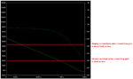
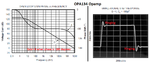
I have designed an amplifier of 133dB of open loop gain. Is too high? The question: more open loop gain means more stability? I have to reduce it?

Screenshot (13).png
 

Your amplifier does not have enough frequency compensation so if its closed loop gain is less than about 500 it will ring and if its gain is 50 or less it will oscillate.
An OPA134 opamp has an open loop gain of about 128dB and phase shift of only 135 degrees when its gain is zero dB at 10MHz. Then it can never ring or oscillate.
Your amplifier has a gain of about 1000 when its phase is 135 degrees so it cannot be used for any circuit using a closed loop gain of 1000.
 
Your amplifier does not have enough frequency compensation so if its closed loop gain is less than about 500 it will ring and if its gain is 50 or less it will oscillate.

I cannot agree.
According to the gain/phase diagram the phase margin at unity gain frequency is app. 30 deg.
So - the circuit with feedback applied will be always stable.
 

Sorry LvW,
I see an oscillator:
 

Attachments

  • amplifier phase margin.png
    amplifier phase margin.png
    57.5 KB · Views: 113
  • OPA134 phase margin.png
    OPA134 phase margin.png
    126.9 KB · Views: 167

Sorry Audioguru,
can't see any oscillation. Severe ringing, yes:

Audiogurus_G&P.png
 
The open loop gain bode diagram in post #1 indicates 18° phase margin for a +1 amplifier. That gives considerable ringing, but is still stable. Power amplifiers are however rarely operated with unity gain. The phase margin for G=+10 is about 75°, indicates no overshoot.

phase margin.png
 
Erikl and FvM,
I was wrong and you are both correct.
I see that at 8MHz the phase is -180 degrees but the gain is less than 1 so it will never oscillate.
When the gain is 10 the phase shift is a little more than 90 degrees which is normal and is stable.
 

Ok thank you all for the answers. How to reduce ringing? I'm actually using darlington as finals in the output stage, should I treat the VAS better? The input stage seems not to be a problem.
 

Reduce ringing by increasing the value of the internal miller capacitor on the VAS. Then the high frequency gain is reduced. Many audio amplifiers have a zobel RC network at the output to ground.
 

I've already a capacitor of 100pF and the zobel network si a 8ohm resistor + 100nF capacitor. But I've done some enhancements. I'm post the screen of:
  • Open loop gain
  • V(out) sine wave with 4 ohm load
  • THD at 20kHz with load
  • FFT with load and with no load at closed loop

Screenshot (20).pngScreenshot (21).pngScreenshot (22).pngScreenshot (23).pngScreenshot (24).png
 

Hi,

I don' t think that with a sine wave input and FFT or THD measurement you get some information about ringing.
But maybe this wasn't your intention.

Klaus
 

Distortion measurements are large signal (transient) analysis and not related to frequency response and stability.

Two additional comments
- THD at 20 kHz isn't of much interest for an audio amplifier, because nobody does hear
- transient analysis with default parameters might be inaccurate when determining low distortion levels 60 dB below fundamental
 

Status
Not open for further replies.

Part and Inventory Search

Welcome to EDABoard.com

Sponsor

Back
Top