1mace1
Newbie level 5
Hello,
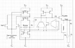
attached you see an architecture of a linear voltage regulator, which should be any load stable.
Can anyone help me to estimate the poles and zeros of this circuit?
I think there should be three Poles and also one zero over C0.
The Pole3 is approximately gmn/(2piCL) if gm is much smaller compared to RL. This Pole is dependent on the current and also on the cap load. But how can I estimate P1 and P2 and also the zero over C0? Is the C0 in the circuit working as miller compensation cap. to split P1 and P2(because Cgs also changes with different currents through pass device) or is this more a cap to control the gat of the pass device?
Thank you