Continue to Site

Welcome to EDAboard.com

Welcome to our site! EDAboard.com is an international Electronics Discussion Forum focused on EDA software, circuits, schematics, books, theory, papers, asic, pld, 8051, DSP, Network, RF, Analog Design, PCB, Service Manuals... and a whole lot more! To participate you need to register. Registration is free. Click here to register now.

ESR meter project from Nuova Elettronica

Status
Not open for further replies.
Re: ESR Meter

Dear Bkelciov,You know what I have to tell you something you are my best buddy aye. I have to thank you for all your responses.

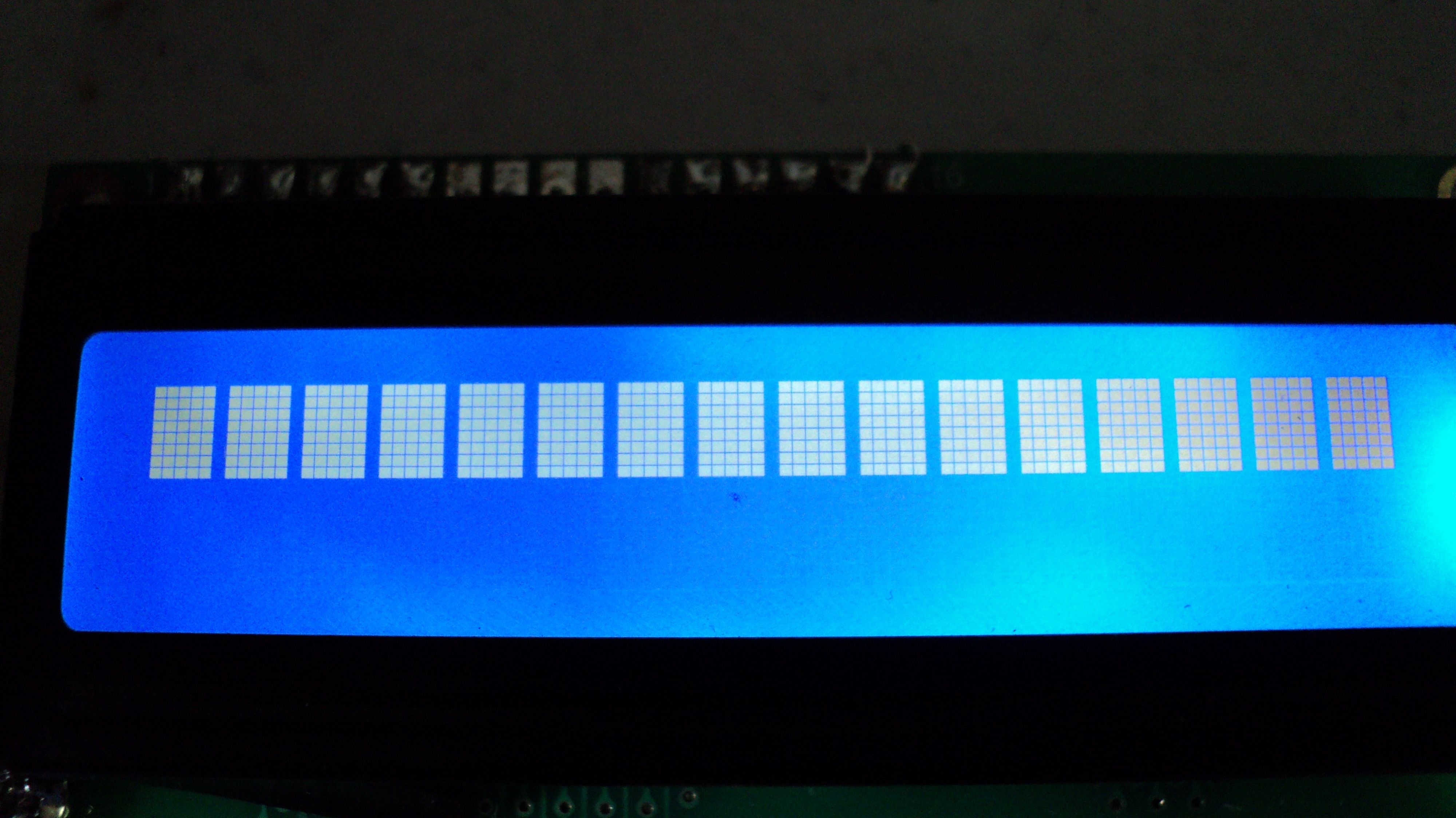
Anyways still no luck :roll:with my ESR but I’m not gonna give-up. You & I ruled out everything. Now my suspicion is it either the LCD or both PIC s I’m using. So I ordered 2 LCD and some PICs from an online store and I hope I’ll receive it by next week.
What else could be aye?

I’ll definitely let you know the feedback. Also this my first project dealing with LCD, I hope this learning curve could give me an opportunity to learn more about some other stuff.

Thank again pal
Haran
 

Re: ESR Meter

Hi Haran
If you build schematics just like it should work, even if there are problems if the input does not matter , if hex.file is good and links to display are correct , alphanumeric characters should be on display , only job is to set the display contrast , for the blue display I used 18K / 1,5 K
I use PIC16F873 or 876 no problem with same hex file .
WBR
Costas
 

Re: ESR Meter

Thanx pal. Well Bkelciov & l ruled out most of the causes but still no luck. So i figured it could be the Display or the PIC. Well i used same blue display with same 18k and 1.5k config all i saw was the top row lit without any characters.
What do you think?

Thanks for you time buddy.
Haran
 

Re: ESR Meter

It look like the PIC does not work. Please post a picture of your device. A focused one, not like the previous. Maybe I can see something wrong.
What programming software do you use? Try "PICPgm programmer".
 

Re: ESR Meter

check if you do not short circuit the wires to the display
or on pcb ...not only the continuity
Costas
 

Re: ESR Meter

It look like the PIC does not work. Please post a picture of your device. A focused one, not like the previous. Maybe I can see something wrong.
What programming software do you use? Try "PICPgm programmer".

Thanks again pal Herewith i'm sending you the closeup shoots. The Pic programmer i used is Enhanced PICkit 2 with Pikit 2 Programmer(Micro Chip). Here is the Hardware link MCUmall Electronics Inc. A low cost EPROM EEPROM Atmel PIC I2C SPI programmer online store


---------- Post added at 14:23 ---------- Previous post was at 14:15 ----------


---------- Post added at 14:26 ---------- Previous post was at 14:23 ----------

check if you do not short circuit the wires to the display
or on pcb ...not only the continuity
Costas

Yes buddy did checked each and every connection patiently more than 5 times didn't miss anything. I posted the closeup photo so you can come up with an idea. Thanks for your help.
 

Re: ESR Meter

Hy Everyone.
I am Emilio from Argentina. I have just finished my ESR meter and neither it works. The same Haran´s problem.
Probably are no set correctly the programming options on my universal programmer (TOP2005+)?? Watchdog, Xtal Oscillator, etc...
I dont know wat to do! Help us! DSCN0535.JPG

Thanks everyone.
 

Re: ESR Meter

To Haran24 and Emiliojuan:
I don't see the 20MHz quartz cristal and the 22pF capacitors.
Try to reprogramm the PIC and check if the fuserbits are set like this:

Try to verify if the PIC is writen correctly: Read from the PIC and save to file and compare the reading from PIC with the original hex file.
The circuit can work with the minimal components, like in this picture:

Good luck.

---------- Post added at 09:09 ---------- Previous post was at 07:42 ----------

Emiliojuan,
Your display is not connected correctly.
Pin1 of the display is first on left. In your picture it looks like is the 3-rd from the right.
 
Re: ESR Meter

a good programmer make auotomatic upload for config.register , the config. option are stored in hex.file

---------- Post added at 09:43 ---------- Previous post was at 09:31 ----------

Are you sure the display is compatible with HD44780
protocol ?
 
Re: ESR Meter

Thank you buddies for your soon reply.
About LCD: Yes, is 44780 compatible (Winstar WH1602A). First pins on left are 15 and 16 (backlight). Pin 1 is the 3rd.
About 20MHz quartz cristal and 22pF capacitors: in the picture, they are behind the tact-switches.
I supose PIC does not work. I will check programmer settings and compare hex files.
okey! let´s work.
see you soon with news
... and THANKS, again.
 

Re: ESR Meter

I've never seen a pic not working ... it's always been somewhere else on the board, or the pic programmer not the correct fuses ...
try to read the pic, and compare the result with what should be in the pic
and tell us the results !
good luck.
 

Re: ESR Meter

I've seen 2 PIC's dead inside 2 same type UPS. Dead means unable to read / write. Don't remember what type / model of UPS.
But in this case, i think is abbout an programming error. I hope they will solve the problem. I work every day with my c-esr meter. My vision abbout electrolytic capacitors changed dramatically since i have this device. It's a "must have" device !!!
Don't give up. Make-it work.
Buddy Bkelciov Thanks for your encouragement. Also i have to thank the other buddies Costas and the guy who gave me an idea to do this project Kripton Thank you guys.

Well there is a progress on my ESR photos attached. The thing is i'm not familiar with pf Caps so i used 220(the digit) after i replaced with (22) the digit i hope it's the right 22pf cap i'm getting the display below.

What i'm getting both rows lit; the first row with a solid box and the bottom with 0 but if press the button for(+) the zero turns into ( ? )when i release it goes to 0 again.

My programmer, it wouldn't work with other software you recommended & its only works with MPLAB IDE and Pickit 2

Also i did checked the fuserbits the way you instructed 3F32 still no luck.

The hex file i compared its puzzling me because the way it looks different the top 2nd and 3rd lines are missing and some other extra keys also showing. So i programmed a different type of PIC 12F683 with fader LED program it also didn't match with original But it's working grate . Exported file attached

Moreover i isolated the circuit on a breadboard just PIC , the LCD, 1N4148,10k,20MHZ, 22PF and 62Ks i'm getting the same display

Any ideas?

Thanks Pal
HaranDSC00132.JPGDSC00135.JPG
 

Attachments

  • Export.txt
    23.3 KB · Views: 149
Last edited:

Re: ESR Meter

Haran24, your "Export.txt" is OK. So, you have a working PIC with a working program. I'll try to change the quartz and elliminate the 22pF on my device to see what is happening.
Pleas tell the name / model of your display. It is 44780 compatible ?
It seem to be a problem with your display. Data lines of the display to data port of the PIC.
 

Re: ESR Meter

I'm also thinking to a lcd that's not fully compatible.
can you try with another lcd (from another brand ?)
 

Re: ESR Meter

Haran24, your "Export.txt" is OK. So, you have a working PIC with a working program. I'll try to change the quartz and elliminate the 22pF on my device to see what is happening.
Pleas tell the name / model of your display. It is 44780 compatible ?
It seem to be a problem with your display. Data lines of the display to data port of the PIC.


Thanks buddies. This is the display i'm using https://www.dipmicro.com/?datasheet=TINSHARP-1602A-01T.pdf .Also the online store where i bought this display says HD44780 is obsolete controller and was replaced by newer backward compatible SPLC780 and ST7066 types. [/U][/B][/B]

Still i'm not trusting the display. i ordered another display . The thing is Canada post on strike so i have to wait until the end of the week. in the meantime I have 2 displays hanging around (Hitachi interface) those from an HP 4100 and 8100 display the problem is it's so hard to trace connections you guys have any idea?

Thanks
Haran
 

Re: ESR Meter

the initialisation method differs from one lcd to another, and this depends from the lcd controler !
when you have a bad init sentence, you get these gray dots on the lcd ..L.
so unless you can / want to / look into the source code of the esr meter to change the init sentence, better wait for a compatible lcd ...
just my 2 cents ...
 

Re: ESR Meter

Haran24, your "Export.txt" is OK. So, you have a working PIC with a working program. I'll try to change the quartz and elliminate the 22pF on my device to see what is happening.
Pleas tell the name / model of your display. It is 44780 compatible ?
It seem to be a problem with your display. Data lines of the display to data port of the PIC.

Hi buddies, Well there is a good news my project succeeded 75% only. Now the display's working and showing everything the problem was there was a invincible solder bridge between D7 & D6 on the display panel PCB continuity tested failed but a magnifier found the bridge.It's all my bad because i didn't solder properly.

Now the problem is it's not showing the capacitance value what could be the problem. Which area it could be? I used several electrolytic caps but it's not showing CX value. photo attached.

Thanks for your precious time
Haran DSC00157.JPG
 

Re: ESR Meter

Check VT1, VD1, VD3 area for other bridges. Then check LM393 area.
Without capacitor on test leads ESR must be greater than 11.xxx
If that picture is without capacitor, then is a bridge in the test leads area.
For calibration, please read the first page of this thread.
 

Re: ESR Meter

Check VT1, VD1, VD3 area for other bridges. Then check LM393 area.
Without capacitor on test leads ESR must be greater than 11.xxx
If that picture is without capacitor, then is a bridge in the test leads area.
For calibration, please read the first page of this thread.

Thanks Pal, Without Capacitor it shows ESR 0.000 and i couldn't find the calibration on page 1


MY CONFIGURATION IS
VT1 = BC327 (is it okay to use this Transistor?)
VD1,VD3 =1N4148

There is no bridges in LM393 VT1, VD1 & VD3 areas now i'm worried what's going on ? Please help me I'm really sorry to bother you my friend

Thanks
Haran
 
Last edited:

Status
Not open for further replies.

Similar threads

Part and Inventory Search

Welcome to EDABoard.com

Sponsor

Back
Top