Continue to Site

Welcome to EDAboard.com

Welcome to our site! EDAboard.com is an international Electronics Discussion Forum focused on EDA software, circuits, schematics, books, theory, papers, asic, pld, 8051, DSP, Network, RF, Analog Design, PCB, Service Manuals... and a whole lot more! To participate you need to register. Registration is free. Click here to register now.

ESP Serial Communication Problem with RS232

Status
Not open for further replies.

htekin42

Member level 2
Joined
Dec 10, 2012
Messages
45
Helped
0
Reputation
0
Reaction score
0
Trophy points
1,286
Activity points
1,699
Hi there,

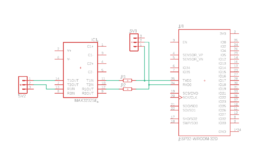
I am trying to design a pcb with ESP32 and using max3232 for serial communication. My problem is when I connect max3232 directly with max3232, I cannot program ESP32 on TTL pin header. When I made a research I need to add resistor between max3232 and ESP32 to program it on TTL side. I could not find any information about defining resistor value. How can I define resistor value between ESP32 and max3232 to program it without any problem on TTL header.

thanks
 

Attachments

  • sch_max3232.PNG
    sch_max3232.PNG
    21.9 KB · Views: 250

Hi,

Whether MAX3232 can communicate with ESP32 depends on the signal voltage specification and the supply voltage of both devices. (besides baud rate, handshaking and so on).

My problem is when I connect max3232 directly with max3232, I cannot program ESP32 on TTL pin header.
What exactly do you mean? Can you show an (almost) complete schmatic.

Klaus
 

Hi Klaus,

My problem is we try to program ESP32 with programming header connected to ESP32 TX-RX line directly. Normally we designed the board as follow. max3232 tin and rout connected to directly to ESP32 pins.

sch_max3232_v2.PNG


When we try to program ESP32 it has communication problem. and I made some research on web and people talking about adding resistor to TTL signal. and we added R1 and R2 as seen on below design. We need to determine resistor value and could not figure out how to determine.

sch_max3232_v1.PNG


As seen in the schematic, we program the ESP32 with programming header.
 

You migh be aware that the programming procedure on ESP-32 involves handling levels at some GPIOs. From your schematic, the U1 esp-wroom-32d device seem rather a module, with nothing connected at remaining pins. Even if you tried to do that with an ESP32 dev board, additional flow control signals from RS-232 would be needed to drive the programming pins from the MCU at the appropriate timming.
 

Hi,

still unclear:
* supply voltages
* programmer connection and signal voltage levels
* MAX3232 to MAX3232 connection

+++
One problem I see: You never must connect two (logic) outputs without short circuit prevention.

Klaus
 

I think it's a fight between the programming hardware and the MAX3232, both are trying to drive the RX pin at the same time. Try adding a resistor in series with the RX output (R2 in your schematic), no need to put one in the TX line. The value will need some experimenting, make it too small and the problem will still exist, make it too big and you will restrict the top speed of the RS232 link. I would suggest trying about 220 Ohms first.

If you are making a PCB, use a removable link, pull it to program and fit it for normal use.

Note that other IO pins have to be pulled high and low at the instant of powering up for the ESP to go into programming mode.

Brian.
 
Hi Brian,

Thanks for your detailed information. Is there any way to determine with calculation or measurement?

Thanks
 

You need only the lower resistor, the upper one is not needed. Maybe you can get some inspiration from an Arduino schematic where Serial is used for programmint to.
 

Programmer Tx drive strength determines the minimal series resistor. I'd go for 1 - 2.2k. Highest RS-232 speed is 920 kBd in case of doubt, no problem with a few k.
 

As stated, it is just Ohms Law, you have two signals driving one pin, one signal from the programmer, one from the MAX3232, you have to ensure the programmer can drive enough current to allow the ESP logic levels to be reached. Adding the resistor limits how much the MAX3232 can 'push' so the programmer can dominate. Unfortunately, when it comes to exact logic levels needed and exact drive currents available, there are manufacturing differences between devices so you have to cater for worst case scenario situations.

There is a possibly an alternative method you can use: Use a second MAX3232 to drive the existing one and pass the programming signals through it so the whole programming sequence is done over RS232 and no resistor is needed at all. The only drawback to that method is that normal programming speed may be compromised but if you keep the wiring length short it might work.

Brian.
 

Status
Not open for further replies.

Part and Inventory Search

Welcome to EDABoard.com

Sponsor

Back
Top