Continue to Site

Welcome to EDAboard.com

Welcome to our site! EDAboard.com is an international Electronics Discussion Forum focused on EDA software, circuits, schematics, books, theory, papers, asic, pld, 8051, DSP, Network, RF, Analog Design, PCB, Service Manuals... and a whole lot more! To participate you need to register. Registration is free. Click here to register now.

Equivalent circuit to a LED for LED Driver Simulation

Status
Not open for further replies.

Meri96

Junior Member level 3
Joined
Dec 3, 2020
Messages
28
Helped
0
Reputation
0
Reaction score
0
Trophy points
1
Activity points
456
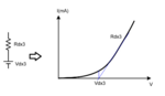
Hello everyone, what I'm wondering is if we need to see the I-V characteristic of the LED in the simulation while doing an LED driver simulation? While designing an LED driver, I looked at the LED datasheet and took the output current as 1.050A and the output voltage as 3.10V and I designed a dc-dc converter. In the simulation of my design, I used the equivalent LED circuit that includes a resistor(0.2ohm) and a dc source(2.6V) (or zener) in order to see the LED characteristic. The circuit I made only provides the 1.050A-3.1V point that I referenced.

When I perform the simulation in this way, do I need to obtain the current-voltage values in the LED I-V characteristic using pwm?

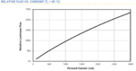
When I also looked at the datasheet, I saw that 100% brightness was achieved at 1.050 A. Logically, shouldn't the LED driver that I made go above 1.050A?

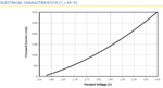
Finally, for the design, they suggested me to take the max voltage value in the table, namely 3.10V, the 1.050A-3.10V values I took as a reference from the table do not seem to meet the I-V characteristic anyway. When I look at the graph, the voltage value corresponding to 1.050A looks like 2.79. For the DC-DC converter design, should I have chosen the output voltage of 2.79 rather than 3.10.
 

Attachments

  • LED-datasheet.PNG
    LED-datasheet.PNG
    34.5 KB · Views: 87
  • V-I.PNG
    V-I.PNG
    39.6 KB · Views: 93
  • Luminous.PNG
    Luminous.PNG
    34.4 KB · Views: 204
  • equivalent circuit to LED.PNG
    equivalent circuit to LED.PNG
    13.2 KB · Views: 115

Hi,
if we need to see the I-V characteristic of the LED in the simulation while doing an LED driver simulation?
depends what informarion you expect from the simulation.

If you are doing stability analysis then you should use a load that comes close to the real load.
--> Not a simple R, but a zener and series R combination.

for stability r = delta_V / delta_I is what matters. Not R = V / I.

Klaus
 

for stability r = delta_V / delta_I is what matters. Not R = V / I.

I took it as 0.2 by calculating over r = delta_V / delta_I . Using the zener in series with this resistance, I chose the breakdown voltage as 2.6. When I used the equivalent LED circuit that I chose connected to the V-I graph, I could not provide all the values of the V-I graph in the simulation. Could it be that my DC-DC converter design is wrong even if it provides 1.050A-3.10V values?
 
Last edited:

First thing is to read the datasheet thoroughly and understand the meaning of terms, e.g. what is typical and maximum voltage for a given LED current. Device parameters undergo type and temperature variation, a model can only represent one parameter set, usually typical parameters. I guess 1.05 A is rated LED current, values up to 3 A are probably only permissible in pulsed opreation, but you'll know when reading the complete datasheet. A diode with series resistors looks like a reasonable model, by adjusting the diode parameters and resistance, you can fit the actual LED characteristic quite accurately, if necessary at all.
--- Updated ---

I could not provide all the values of the V-I graph in the simulation
Means what exactly? Which LED current range are you trying to achieve? Is there any reason to exceed rated continuous current in your application?
--- Updated ---

I reviewed the XP-L2 datasheet and found that 3 A is feasible as continuous current, but only with effective heatsinking, as shown in the thermal design graph.

1617715197173.png
 
Last edited:
  • Like
Reactions: Meri96

    Meri96

    Points: 2
    Helpful Answer Positive Rating
It is the first time I am working on the LED driver and I thought it should provide the V-I characteristic to make sure the circuit I designed for the nominal current is correct. In other words, I thought that as the duty ratio changes, I have to obtain the current-voltage values on the V-I graph. I know that when doing brightness control with PWM, I can increase or decrease the LED brightness by changing the duty ratio at fixed frequency. For this, I know that I need to change the duty ratio between 0% and 100% and make the current on the led change between 0 and 1.050A. While doing this, I thought that the output voltage for 500mA for example should be about 2.7V according to the graph. Actually, this is the result that I said I could not achieve.
--- Updated ---

I reviewed the XP-L2 datasheet and found that 3 A is feasible as continuous current, but only with effective heatsinking, as shown in the thermal design graph.

Well, wouldn't that be a problem if the LED that needs 1.050A for 100% brightness is continuously fed at 3A? Isn't LED life shortened? As I said I might be asking simple or silly things, I am new in this field, thanks for your patience and answers :)
 

I thought that the output voltage for 500mA for example should be about 2.7V according to the graph.
Should be the case if you are 1. feeding continuous DC current to the LED and 2. model the LED I/V curve exactly. As for the first point, I don't know your driver circuit. Regarding second point, the voltage source plus resistor doesn't model the LED characteristic well, but probably good enough for basic testing of your driver. An exact model whould better use a SPICE diode.
 

generally with LED circuits...stability is not an issue. A LED load is not a dynamic load (not really), so you can make your feedback loop slow and easy to do.......you wont have to worry too much about compensation.

If you are doing PWM dimming, then many led drivers "freeze" the error amplifier output during the led-off intervals, so it comes back on without having to hunt for a new control value...most linear.com led drivers do this.

Many led drivers use simple hysteretic control, and these are ideal for pwm dimming as they come straight back on at the right current level...perhaps the current level needs some general "minding" by a micro , but thats it.

and of course, even if you're flashing leds on and off...you can use feedforward, as you actually know exactly when you will flash it back on. I did one flashing led driver and it had a slow, super-stable feedback loop....i zero'd the error amp output just before turnimg the led back on...so that it soft started on every time and didnt have overshoot in its current.

So basically, as you know, slow feedback loops are easy to make stable...and you can make led feedback loops very slow.

I shouldnt be saying it, but many engineers just hack in a few compensation Rs and Cs and stabilise led drivers with a titchy bit of value tweaking, then ship to customer. No need to get your eigenvectors out for stabilising led drivers....and the state-space equations can be ditched too...your books on the PWM switch model can be temporarily binned
 
Last edited by a moderator:
  • Like
Reactions: Meri96

    Meri96

    Points: 2
    Helpful Answer Positive Rating
Status
Not open for further replies.

Part and Inventory Search

Welcome to EDABoard.com

Sponsor

Back
Top