Continue to Site

Welcome to EDAboard.com

Welcome to our site! EDAboard.com is an international Electronics Discussion Forum focused on EDA software, circuits, schematics, books, theory, papers, asic, pld, 8051, DSP, Network, RF, Analog Design, PCB, Service Manuals... and a whole lot more! To participate you need to register. Registration is free. Click here to register now.

EPROM compatibility, use different eprom in circuit?

Status
Not open for further replies.

neazoi

Advanced Member level 6
Joined
Jan 5, 2008
Messages
4,122
Helped
13
Reputation
26
Reaction score
15
Trophy points
1,318
Location
Greece
Activity points
36,951
Hello,
I have a circuit that uses the 2532 eprom. The author has modified it to use the 2732 eprom with a little bit of rewiring


Since I have a 2564 eprom available I would like to use this instead of the 2532 and 2732 ones.
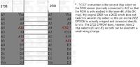
I have found this guide which spots the differences between the 2732 and 2764
**broken link removed**

I need to ask, If I just connect the relevant pins of the 2764 to the 2732 circuit, will I be able to use the 2764 in place of the 2732?

Or does it need any other change?
 

Yes, it will work. I often use chips as big as 27512 to replace smaller ones. Just wire the data pins as before and the address pins as before. Connect the extra address pin on the 2764 to ground and make sure you store the data in the lower part of the EPROM. You can think of the 2764 as being two 2732s with A12 selecting the top or bottom half of the storage space.

Brian.
 
  • Like
Reactions: neazoi

    neazoi

    Points: 2
    Helpful Answer Positive Rating
how can I store the data in the lower part of the EPROM? Is there any specific thing I need to do when burning the rom into it?

A12 will be connected to ground as well for selecting the lower part?
 

If you load the program at address zero as you normally would, because it is only half the size of the new IC, it will only load into the bottom half of the storage space. If you have an option to set the load address, just leave it at zero as you would with the 2532.

Each time the size of a memory doubles, as it does between the 'x32' and 'xx64' it needs another address line to allow all the capacity to be reached. With A12 tied to ground, A0 to A11 will access addresses 0000 to 0FFF (as in the 2532) and with A12 tied to VCC, A0 to A11 will access addresses 1000 to 1FFF, in other words the next 4K block above the first one.

In very early days of EPROMs when they were expensive and in short supply, it wasn't uncommon to see a 2764 made by soldering two 2732 ICs, one on top of the other. All pins were soldered together except the -CE pins which were wired to an inverter and fed from the A12 pin on the socket. The idea was that A12 controlled which of the two smaller ICs was active at a time. As far as the socket was concerned it had a 2764 plugged into it.

Brian.
 
  • Like
Reactions: neazoi

    neazoi

    Points: 2
    Helpful Answer Positive Rating
This is very usefull information!
So basically I need to burn The rom as I would do in an ordinary 2732 eprom (the lower part is the first to write data by default) and then connect A12 to gnd to force the reading from the lower part. Am I getting this right?
 

Absolutely right !

You must tell the programmer you are using a 2764 as well, it needs to know what the real type of IC is because they have built-in identification. There is a method of reading back the manufacturer code and a product code from inside the IC, the programmer will do this to check it matches the type you selected. If you try to program a 2764 with the settings for a 2532/2732 it will tell you it's the wrong device, even if the program fits inside it properly.

Brian.
 

    V

    Points: 2
    Helpful Answer Positive Rating
Status
Not open for further replies.

Part and Inventory Search

Welcome to EDABoard.com

Sponsor

Back
Top