Continue to Site

Welcome to EDAboard.com

Welcome to our site! EDAboard.com is an international Electronics Discussion Forum focused on EDA software, circuits, schematics, books, theory, papers, asic, pld, 8051, DSP, Network, RF, Analog Design, PCB, Service Manuals... and a whole lot more! To participate you need to register. Registration is free. Click here to register now.

Emitter follower as current booster

Status
Not open for further replies.

vinodquilon

Full Member level 3
Joined
Oct 24, 2009
Messages
158
Helped
2
Reputation
4
Reaction score
2
Trophy points
1,298
Activity points
2,558
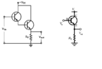
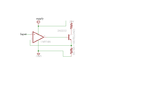
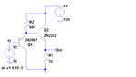
Consider the following Common Collector & Darlington emitter follower circuits,

CASE 1:
Let V(in) = 5V
Vcc(supply) = 10V
Emitter(load) resistance = 100 ohm
thus, V(out) should be 5V (following input)
Corresponding Load current will be 5/100 = 50 mA

CASE 2:
Let V(in) = 5V
Vcc(supply) = 10V
Emitter(load) resistance = 33 ohm
thus, V(out) should be 5V (following input)
Corresponding Load current will be 5/33 = 152 mA

Which source will provide this additional current requirement [Vcc or V(in)] ?
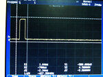
 

Attachments

  • 555 load.png
    555 load.png
    13.5 KB · Views: 120

As i understand, you are asking which voltage source is mainly sourcing current to the load.
It is Vcc mainly, proportional to current driven by Vin source.
As you know ie=(beta+1)*ib and ic= beta*ib, this is coming from the collector node and Vcc is sourcing it.
 
As i understand, you are asking which voltage source is mainly sourcing current to the load.
It is Vcc mainly, proportional to current driven by Vin source.
As you know ie=(beta+1)*ib and ic= beta*ib, this is coming from the collector node and Vcc is sourcing it.

That is I have to set the current limit of supply to above 152mA and don't bother about base current


I want the output should exactly be 5V not (5-junction drops). So that I have to add extra junction drops to source volts. But my source is fixed at 5V.

Shall I design one unity gain Op Amp summer with one 5V and other fixed .7 or 1.4V inputs to feed the emitter follower ?
__________________
 
Last edited:

To get no voltage errors, you'll want to use a feedback amplifier with the current booster inside the feedback loop. Or a power OP with sufficient output current.
 
FvM's solution is probably best, but just for interest another option is to use a Baxandall super-pair as shown below. The two VBEs cancel out, but not perfectly - there'll still be a bit of offset.

 
Output is not following the input

To get no voltage errors, you'll want to use a feedback amplifier with the current booster inside the feedback loop. Or a power OP with sufficient output current.

I have setup the Op Amp-Current booster circuit as shown below using LM324 & 2N2222 for loads 33/68/100 Ohms one at a time.

But the output voltage is not following the input as shown below:

INPUT(40mA max)// EMITTER VOLTAGE// DEVIATION //SUPPLY(10V/200mA max)

0 // 0 // 0 // 10,< 100mA

0.5 // 0.4 // 0.1 // 10,< 100mA

1 // 0.9 // 0.1 // 10,< 100mA

1.5 // 1.3 // 0.2// 10, 100mA

2 // 1.8 // 0.2 // 10, 100mA

2.5 // 2.3 // 0.2// 10, 100mA

3 // 2.7 // 0.3// 10, 100mA

3.5// 3.2 // 0.3// 10, 100mA

4// 3.6 // 0.4 // 10, 200mA

4.5 // 4 // 0.5 // 10, 200mA

5 // 4.3 // 0.7 // 9.8, 200mA

5.5 // 4.3 // 0.7 // 9.8, 200mA

6 // 4.3 // 0.7 // 9.8, 200mA

6.5 // 4.3 // 0.7 // 9.8, 200mA

7 // 4.3 // 0.7 // 9.8, 200mA

7.5 // 4.3 // 0.7 // 9.8, 200mA

8 // 4.3 // 0.7 // 9.8, 200mA

8.5 // 4.3 // 0.7 // 9.8, 200mA

9 // 4.3 // 0.7 // 9.8, 200mA

9.5 // 4.3 // 0.7 // 9.8, 200mA

10 // 4.3 // 0.7 // 9.8, 200mA

Anomalies:
1. Output is not following the input
2. After 5V input, the output is struck at 4.3V
3. Supply voltage dips to 9.8V when input is >= 5V
4. Deviation incraeses as the input voltage and set at 0.7 level
5. The measurement is repeated for inputs set at 10mA max & 100mA max. But the issue continues.
6. Can I use complementary emitter follower for my above application by leaving the Op Amp?
 

Attachments

  • current booster.png
    current booster.png
    10.9 KB · Views: 105
  • current booster1.png
    current booster1.png
    15 KB · Views: 106

No clear results reported (e.g. actual load resistance unknown).

It's clear by the design of your circuit, that the output will saturate above a certain voltage, but the low voltage numbers (up to about 3 V) make no sense at all. There is probably an anomalie not understandable from the circuit diagram.

"Supply voltage dip" suggests an unsuitable power supply. Nothing is said about it, so we can just say "try with a different one".

It's completely unclear to me what you mean with "input set to 10 or 100 mA".

1. For my application voltage is also important, that is I don't want to drop my voltage by 0.7v at output. Output should be same as input for three loads 33/68/100 ohms (one is connected at a time).
note: my input would be 0 to 5V in 0.5V steps, then I expect 0, 0.5,1.0,1.5,2.0,2.5,3.0,3.5,4.0,4.5, and 5.0 at outputs for all the loads(common supply voltage settings for all the three loads. i.e, 10V/160mA max).

2. Anomaly could be due to change in emitter and collector leads, I will check it.

3. "input set to 10 or 100 mA"---input is fed by a dc source with max current setting 10 or 100mA and voltage is stepped by 0.5v form 0 to 5v by turning external knob
 

I am using 1ms single pulses from monoshot(with 0.5v stepped out) as the input to the op-amp and monitoring voltage at emitter on CRO.


Can OP-AMP & transistor can track the 1ms pulse change?
 

Your output will be 0.6V less than the input, due to the diode drop through the B-E junction.

Similarly the darlington arrangement will drop 1.2 or 1.3 V.
 

I got it !

It was my mistake. I got interchanged the collector and emitter. Now I rectified the problem and the output follows input.

See the attachment for my project.

1. First I have implemented LM324-2N2222 portion without R9 and 50K on a bread board

2. Set supply at 10V with 200mA current limit

3. Gave inputs to the 3rd pin of Op-Amp using a dc source and varied the dc volts in 0,0.5,1,1.5,2,2.5,3,3.5,4,4.5,& 5 to simulate variable mono pulses

4. WoW! :)output following the input with saturation occurs at 7.77V

5. Connected the 100R resistor network as shown in the figure with one end at ground and other end connected to dc source(set at 5V) mentioned in 3rd point to simulate the mono pulse

6. Connected voltage legs of the ladder directly to 3rd pin of Op-Amp without 50K.

7. WoW! output following the input for 0,0.5,1,1.5,2,2.5,3,3.5,4,4.5,& 5 at different positions of the resistor ladder

8. Tommorow I am going to implement 1ms 555 monoshot or 1ms 74123 monoshot(additional 7805 IC needed to power it) on separate bread board and will cascade all three sections(1ms monoshot + Resistor ladder + Op-Amp_BJT) to form the final project. Hope it will work fine.

ANOMALIES OBSERVED::-(

1. 50K is rejected intentionally and connected the voltage legs of the ladder to the Op-Amp directly. This is to avoid the disturbance to the ladder resistors when 50K comes in parallel to them as I want exact 0.5V divisions of 5V.
But this causes the emitter volatge to goes to saturation(7.77V) when 3rd pin of Op-Amp not connected to any points.(floats)
To avoid this can I connect a high value resistor like 100K between 3rd pin and ground permanently without disturbing both ladder and Op amp.

2. 1ms pulses are almost too short for a lousy old LM324 opamp.
Which Op Amp should I use to transfer 1ms varying amplitude pulses to load fluently with 0 to 5 volt in/out capacity ?
 

Attachments

  • 555 v3.1.png
    555 v3.1.png
    18.2 KB · Views: 112

3rd pin of Op-Amp not connected
No idea what you mean. Neither can I imagine a reasonable purpose to unconnect one of the 5 OP pins.

LM324 should be fine for milliseconds speed. You didn't mention a particular problem or a requirement that isn't met by the device.
 

Output

Here is my output for the circuit implemented using 555-LM324-2N2222 with Connection taken from 4.5V plug of the resister ladder.

Anomalies observed:

1. Even if I have implemented one Differentiator circuit, according to the manual pushing speed of the trigger switch the 1ms output duration is 'slightly' varying and some disturbances occur in the output pulse

Can I solve this by incorporating 74LS14 schmitt trigger inverters(2 Nos) in series with Microswitch.

2. Some noise like spikes are there at high level and low level of the output pulse. Is this is due to circuit or measurement setup ?

(0.5V voltage divisions from 5 to 0V are perfectly taking place with the use of resistor ladder having resistors of tolerance 0.01%)
 

Attachments

  • mono pulse1.jpg
    mono pulse1.jpg
    652.7 KB · Views: 98
  • 555 v3.1.png
    555 v3.1.png
    18.2 KB · Views: 107

I am using non-electrolytic capacitor as timing capacitor connected to pin 7 of 555. Is it OK?
 

Here is the micro switch debouncer circuit.


We have disused about the slew rate and rail in/out capacity of the op-amp to sync with 1ms pulses ranging from 0-5V in 0.5V steps. Can 2N2222 power transistor sync with voltage levels and timings ? Is there any better options ?

- - - Updated - - -

Here is another one...
 

Attachments

  • vinodquilon's debouncer.png
    vinodquilon's debouncer.png
    33.2 KB · Views: 134
  • 555 v4.png
    555 v4.png
    14.6 KB · Views: 105

I dont want to connect a capacitor across a switch directly as the switch shorts out the cap when it is closed. That's not that good of an idea. However, with a small resistor like 100 ohms in series with the cap, all is well.

If I connect 100 Ohm in series with the capacitor across the switch, will it affect the Lower Threshold Point of Schmitt trigger inverter ?
 

Attachments

  • 555 v4.1.png
    555 v4.1.png
    14.8 KB · Views: 113

Status
Not open for further replies.

Part and Inventory Search

Welcome to EDABoard.com

Sponsor

Back
Top