Welcome to our site! EDAboard.com is an international Electronics Discussion Forum focused on EDA software, circuits, schematics, books, theory, papers, asic, pld, 8051, DSP, Network, RF, Analog Design, PCB, Service Manuals... and a whole lot more! To participate you need to register. Registration is free. Click here to register now.
I am building a power supply of 24V,i saw some schematics where the EMI filters are used, How do we calculates the values were not mentioned. And What are the things needed to be taken care while design EMI filter.
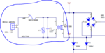
that's not an EMI filter. A filter would include at least one length element e.g. an inductor and one shunt element e.g. the shown capacitor.
The shown components are used to protect the circuit against high current and voltage events. F1 seems to be a thermal fuse, which blows if the input current is to high. V1 is a varistor/MOV which protects the circuitry against high voltage peaks by providing a low resistive path.
So for example, if the voltage is too high V1 kicks in and provides a low resitive path, which causes a high current wich might destroy F1, depending on the reaction time of the fuse and duration of the high voltage event.
BR
--- Updated ---
... C1 represents a classical X-capacitor which has indeed an EMI supression purpos.
L1 and C1 can be considered as EMI filter elements.
Allthough L1 is a common mode choke, it has some differential inductance and is in so far filtering differential mode interferences in combination with C1. The common mode inductance is acting in combination with line common mode impedance.
L1 and C1 can be considered as EMI filter elements.
Allthough L1 is a common mode choke, it has some differential inductance and is in so far filtering differential mode interferences in combination with C1. The common mode inductance is acting in combination with line common mode impedance.
Yes,the schematic is of a TI Evaluation board. I was facing issue in determining the value of L1 and for that i need to know how the value needs to be calculated.
Common mode chokes are usually selected for rated current and have typical inductance values. I don't know what your specific problem in "determining the value of L1" is. Copying values from a known working design, e.g. the said evaluation board that comes with EMI measurements would be a practical approach. To calculate anything on your own, you need to understand the mechanism of EMI propagation first, common and differential mode impedances, EMI standards, artificial networks (LISN) used for measurement etc.
the DM inductance of the CM choke ( usually about 5% ) forms a DM filter with the cap on the mains, the CM choke attempts to reduce CM ( common mode ) noise to the mains - it is an EMC filter - but perhaps not a very efficacious one.
the DM inductance of the CM choke ( usually about 5% ) forms a DM filter with the cap on the mains, the CM choke attempts to reduce CM ( common mode ) noise to the mains - it is an EMC filter - but perhaps not a very efficacious one.
This site uses cookies to help personalise content, tailor your experience and to keep you logged in if you register.
By continuing to use this site, you are consenting to our use of cookies.