Continue to Site

Welcome to EDAboard.com

Welcome to our site! EDAboard.com is an international Electronics Discussion Forum focused on EDA software, circuits, schematics, books, theory, papers, asic, pld, 8051, DSP, Network, RF, Analog Design, PCB, Service Manuals... and a whole lot more! To participate you need to register. Registration is free. Click here to register now.

EMC filter for conducted emissions

Status
Not open for further replies.

Jester

Full Member level 6
Joined
Aug 18, 2012
Messages
377
Helped
7
Reputation
14
Reaction score
7
Trophy points
1,298
Location
.
Activity points
4,754
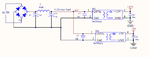
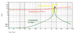
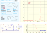
Can anyone recommend a design tool for optimizing a conducted emissions filter?

This is low power for a 50V to 5V LM46000 simple switcher, < 2W

Thanks
 

I found a paper from TI that focuses on differential mode noise and filtering for buck converters.

I came up with 3.3uF 10uH 15uF. The paper assumes the filter will connect directly to the input capacitor of the converter, however in my case there is a bridge rectifier feeding the simple switcher. Should the damping capacitor be moved to to the DC side of the bridge?

filter1.png

https://www.ti.com/lit/an/snva489c/snva489c.pdf
 

The filter is meant to be on the DC side of the bridge. It will go up in smoke if you put it on the AC side with the suggested values.
 
E-design, I need to stop posting when I'm too tired.

Does this look reasonable, or should each DC converter have a separate filter?
 

Attachments

  • filter2.png
    filter2.png
    22.3 KB · Views: 144
You should verify performance through actual measurement using an LISN device. One can do calculations and simulations, but it must be verified by actual measurements.
 

E-design,

Yes I appreciate that, I just want to at least have something in place for the pre-scan. Any thoughts on using one filter for both converters in the last image?
 
You must make sure that the output impedance of the filter stays well below the total input impedance of the switchers otherwise some instabilities can occur.

In the attached plot of a typical power supply measurement, you can see that the impedance of the filter goes higher than that of the psu under test. This will cause a problem and must be prevented.
 

Attachments

  • filter_psu_impedance.png
    filter_psu_impedance.png
    253.1 KB · Views: 123
Last edited:
E-design,

Thanks for continuing to tutor me.

The damping capacitor Cd is supposed to lower the Q (green peak) to minimize changes to the converter loop gain.

I did not annotate the schematic with the details of Cd, it was chosen with fairly high ESR of 1.2Ω to soften the peak.

How does one go about calculating the impedance of the power supply (red line)?
 
These types of **broken link removed** can only be accomplished accurately with the aid of an FRA (Frequency Response Analyzer). You will typically measure the variation in the input current against that of a perturbation signal injected into the input. From this, you can calculate/plot the input impedance over some frequency span.

Unfortunately FRA's don't come cheap.
 
Interesting.

I posted another question in this forum regarding 60Hz ripple on the input to a SMPS, it would be great if you could share your expertise regarding that question. Assuming for a moment the SMPS can deal with the large input ripple, it does raise another point in that a large bulk capacitor directly after the bridge would now be in parallel with the capacitor that forms the EMC filter shown above. This simple little circuit is not so simple.
 
The bulk capacitor directly after the bridge should have a very small influence on the output impedance of the filter. The main contributors will be the L and C on the output of the filter.
 
I'm starting to get a better feel for this. I ran a few simulations and this is what I observed:
First simulation is the response of the PI filter in the RECOM document with input and output as shown.
- Looks similar to image in post 7
- fr at about 4kHz
- ESR of C2 has very significant effect on the Q of the LC. makes we wonder if its not wise to add a small value resistor in series with Cd to allow for control of Q just in case stability issues arise?

2nd simulation is looking the other way, how much of the 370kHz noise from the converter makes it back out to the line?
- the filter seems quite effective >50dB @ 370kHz
- The value of C1 is interesting:
- if too small say 3uF the resonant peak starts to grow significantly and fr shifts up slightly
- if large the peak disappears, and the resonant peak shifts down slightly.
- so it appears a large input capacitor (C1) is both good for stability and EMC reduction

1) Does this sound correct, or am I out in left field again?
2) If I have two of these SMPS both running at about 350kHz, is there any reason I can't feed both from one filter?
I'm mostly concerned with impact on stability of the SMPS's.
 

Attachments

  • FilterEDA.png
    FilterEDA.png
    136.5 KB · Views: 117
Last edited:
You will only know if your assumptions and modeling are correct by verifying performance in the lab. Sometimes we see results that we never expected. Often the L in the filter will be damped by placing a resistor in parallel to reduce the Q.
 
E-design,

I added a resistor just in case.

I need to add a large 470uF or so capacitor between the bridge and the input to this filter to smooth out the dips from the incoming 120Hz. I don't see any reason why I can't eliminate the 3.3uF capacitor in the original filter, do you agree?
 

Yes, I don't think the 3.3 uF will serve any purpose when paralleled with the 470 uF.
 

Status
Not open for further replies.

Similar threads

Part and Inventory Search

Welcome to EDABoard.com

Sponsor

Back
Top