Continue to Site

Welcome to EDAboard.com

Welcome to our site! EDAboard.com is an international Electronics Discussion Forum focused on EDA software, circuits, schematics, books, theory, papers, asic, pld, 8051, DSP, Network, RF, Analog Design, PCB, Service Manuals... and a whole lot more! To participate you need to register. Registration is free. Click here to register now.

EM simulation on ADS of simple CPW structure

Status
Not open for further replies.

ab_basu

Newbie level 5
Joined
Jun 21, 2019
Messages
9
Helped
0
Reputation
0
Reaction score
0
Trophy points
1
Activity points
92
Hi,

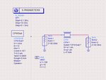
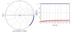
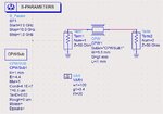
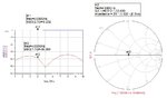
I am new to simulation in ADS, and I want to do EM simulation of a basic CPW structure. I need a step-by-step guide to do so. I used line calculation to optimize Lwisth and length. I have attached the circuit and basic S-parameter of the design (Fig. 1 and 2). Then I generate a layout, that came like Fig. 3. What to do after this? I tried to use substrate as a Si substrate with 1 mm thickness. But I think I am doing something wrong. Please I need it urgently. Somebody, please help.
 

Attachments

  • 1.JPG
    1.JPG
    66 KB · Views: 231
  • 2.JPG
    2.JPG
    46.8 KB · Views: 216
  • 3.JPG
    3.JPG
    27.2 KB · Views: 220

The line dimensions and substrate information of the CPW transmission line that you set are not meaningful.
Use a transmission line calculator before doing these settings.
Try using the settings in the example I attach.
 

Attachments

  • CPW.jpg
    CPW.jpg
    103.5 KB · Views: 181
  • Sp.jpg
    Sp.jpg
    70.2 KB · Views: 155

But I think I am doing something wrong.

Yes indeed!

As you can see in layout, there is no side ground created. Layout just draws a zero width line to indicate where side ground edge starts. The second issue is that not only the side ground is missing, the ground pins are missing as well. So your simulated structure is a microstrip line, with ground return at the bottom of the substrate.

You can use my application note on parameterized layout for EM in ADS:
but CPW is a bit tricky.

If you do NOT need to include metal thickness, and zero width EM solution is good enough, you can use the lot mode in Momentum where you draw the SLOT instead of the conductor. Then you could use (abuse) the MCLIN microstrip model to generate the layout (representing the CPW slot!).

There should be some instructions in ADS online help on CPW simulation using the slot mode.

Good luck!
Volker
 

    ab_basu

    Points: 2
    Helpful Answer Positive Rating
Yes indeed!

As you can see in layout, there is no side ground created. Layout just draws a zero width line to indicate where side ground edge starts. The second issue is that not only the side ground is missing, the ground pins are missing as well. So your simulated structure is a microstrip line, with ground return at the bottom of the substrate.

You can use my application note on parameterized layout for EM in ADS:
but CPW is a bit tricky.

If you do NOT need to include metal thickness, and zero width EM solution is good enough, you can use the lot mode in Momentum where you draw the SLOT instead of the conductor. Then you could use (abuse) the MCLIN microstrip model to generate the layout (representing the CPW slot!).

There should be some instructions in ADS online help on CPW simulation using the slot mode.

Good luck!
Volker
Thank you for your help and sorry for the late reply.
Sorry, I did not get your point. Why the side grounds are not created?

I need to simulate the CPW with the dimensions measured from Line Cal. Please guide me step by step.
I want to
 

ADS auto-generated layout does not draw side ground AREA because that can be large or small, depending on other elements in your layout. Only the distance to the side ground is cleary defined. So you must add metal manually in ADS layout.

There are some nice "Learn ADS in 5 minutes" tutorials in youtube, if you are interested to learn about ADS layout.
Sir,

Thank you so much for your suggestion. I will try it and get back to you.
 

Status
Not open for further replies.

Part and Inventory Search

Welcome to EDABoard.com

Sponsor

Back
Top