Continue to Site

Welcome to EDAboard.com

Welcome to our site! EDAboard.com is an international Electronics Discussion Forum focused on EDA software, circuits, schematics, books, theory, papers, asic, pld, 8051, DSP, Network, RF, Analog Design, PCB, Service Manuals... and a whole lot more! To participate you need to register. Registration is free. Click here to register now.

[SOLVED] Electronic instrumentation. Reactive sensor

Status
Not open for further replies.

CataM

Advanced Member level 4
Joined
Dec 23, 2015
Messages
1,275
Helped
314
Reputation
628
Reaction score
312
Trophy points
83
Location
Madrid, Spain
Activity points
8,409
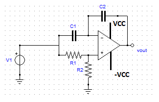
One problem of my exam is the following one:


If the sensor's variable capacitance varies like this: C=Co(1+x), for a linear output, must be placed where C1 is on the schematic. (I do not think this is important for what I will ask below though)

There were several questions to do to this circuit but one of them is the following one:

Will this circuit work in real life? Briefly explain your answer.

So to that question I did not answer anything... could someone tell me what would your answer be if you were in the exam in my place?
 

Your input appears to be DC. The two capacitors are in series, and no resistor to create an RC time constant. With real hardware we don't know what DCV charge they start out with, and therefore their resulting DCV charge level is not predictable.

There might be some voltage-balancing influence from the input resistance, if it is sufficiently low, but that is not normally much of an influence in an op amp.
 

The circuit can't work because it's missing a DC bias. The problem is independent of using AC or DC signals.
 

The circuit can't work because it's missing a DC bias. The problem is independent of using AC or DC signals.

Are you referring to the power supply of the OP amp that I did not show ? I also omitted that for simplicity but it actually was in the original schematic.

If you are referring to an additional DC bias, could you tell me where should be placed ?

- - - Updated - - -

This is the original schematic. (No bypass on power supply, however, that should not be the major problem)


The circuit needs negative DC feedback to set the bias point. Could be a high ohm resistor parallel to C2.
 
  • Like
Reactions: CataM

    CataM

    Points: 2
    Helpful Answer Positive Rating
The input bias current on the inverting input will cause the op amp output to latch up uncontrollably.
As previously stated the inverting input MUST have a source of dc bias for this circuit to operate.

So regardless of any other consideration the whole circuit is a non starter.
 
  • Like
Reactions: CataM

    CataM

    Points: 2
    Helpful Answer Positive Rating
The circuit needs negative DC feedback to set the bias point. Could be a high ohm resistor parallel to C2.

Ok, but where does the DC come from ? DC offset of the OP amp maybe ?
 

No OP can work without a DC path for the input currents.
 
  • Like
Reactions: CataM

    CataM

    Points: 2
    Helpful Answer Positive Rating
Status
Not open for further replies.

Similar threads

Part and Inventory Search

Welcome to EDABoard.com

Sponsor

Back
Top