Continue to Site

Welcome to EDAboard.com

Welcome to our site! EDAboard.com is an international Electronics Discussion Forum focused on EDA software, circuits, schematics, books, theory, papers, asic, pld, 8051, DSP, Network, RF, Analog Design, PCB, Service Manuals... and a whole lot more! To participate you need to register. Registration is free. Click here to register now.

Electronic Fuse Circuit

Status
Not open for further replies.

tdock

Newbie level 2
Joined
Nov 2, 2007
Messages
2
Helped
0
Reputation
0
Reaction score
0
Trophy points
1,281
Activity points
1,307
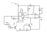
Hello edaboard forum, this is my first time posting. Attached is a circuit I’ve been trying to develop for over current protection. The idea is to replace a resettable fuse (PTC) to get faster reaction time and less temperature dependence. Please read through the operation description and view my concerns. I am some what at a loss as to how these can be overcome. Any suggestions would be greatly appreciated. Thank you.
 

Attachments

  • ElectronicFuse.pdf
    14.3 KB · Views: 146

The output of the opamp changes very fast from 0 to positive supply (max output depending on the opamp),
you are using a comparator so you will get almost the supply voltage.
Depending on which input is higher you will get one of the two voltages, not a voltage between them.
If your pulses touch the current limit then increase the current limit.
For a low Rds on mosfet if the gate voltage is in the proper level the voltage drop will be low,
according to the datasheet of your mosfet you will have a voltage drop of 0.2v at 2A with a Vgs of 5-10v.
You will have an additional voltage drop on the resistor , up to about 0.5v.

Alex

---------- Post added at 17:09 ---------- Previous post was at 16:07 ----------

I also think you should use smaller resistors in the output (the datasheet uses a typical 3K from output to positive supply)
so that you can provide more current to charge/discharge the gate capacitance faster.
Use 2 resistors 1k+2k or other values depending on your voltages so that you keep the gate voltage below 20v.

Alex
 
Last edited:

Thanks Alex,
I can understand the benefits of lowering the output resistor to allow for faster switching. Thanks for the advice.

I also think part of the problem is the voltage divider on the comparator output. Though it is needed to prevent Vgs from exceeding +/-20V it also limits the voltage level on the gate from rising above 19.5V. This is only a Vgs difference of 4.5V not allowing the device to shut completely off. Is there anything I can do about this? Remember the circuit needs to work from 7V to 24V.

Tim
 

tdock,

Will this circuit start up properly? When you apply the input voltage Vdc, both inputs of the comparator are at exactly at 0V. If the offset of the comparator is so that the output is high (impedance), then, the mosfet will never turn on.

Moving R1 to the input side (left to the mosfet) can maybe help, because it stays under tension, even when the mosfet is off.

Stefaan
 

There's one thing a fuse will do for you, that none of the
semiconductor based resettable solutions will. That is,
once overcurrent, it stays open and will stand off kV
without changing its mind. Try that with a transistor, if
you like that kind of smell.

It's also polarity insensitive and needs no secondary
power supply.

Sometimes fancier is not better.

But the scheme you show is the basic idea of all sorts
of power management products (hot-swap, self-
protecting power supplies, etc.). What it not, is a
fuse equivalent.
 

I see several issues with the presented circuit:

- As mentioned by svhb, it will only start up by chance. You need an artificial input offset that's present already at zero output voltage

- An electronic fuse should work without a huge heatsink required for about 54 W power dissipation

- I won't like the inaccurate and temperature dependent current threshold set by a diode forward voltage

- Using a comparator in a feedback circuit involves instability. The peak current of respective oscillations will be most likely higher than the intended threshold.

- C19 shouldn't have a value of 100 µF

A strong foldback characteristic or a latch can reduce the power MOSFET dissipation, but it may prevent regular circuit startup in case of a capacitive load. Ideally, a latching fuse circuit would be combined with a delayed trigger, allowing a limited current for a few milliseconds and disconnecting the load, if the overload lasts. The current limiter should use a compensated feedback loop with an OP instead of a comparator. The delayed latch can be also implemented in a digital control circuit or a small µP.
 

Yes, i think oscillation will be a problem because as soon as the current is dropped below the current threshold the circuit will be on again and this will be endless as long as the short-circuit (or excessive current) exist.
This will overheat the mosfet because it will be involved in a very fast on/off loop.
I have done a similar circuit with an opamp in a chopper circuit (motor current limiting) but the opamp disabled the output of a flip-flop which was set on again with a trigger clock, so there was a delay and no oscillation could occur.
I don't know if there is a way to "lock" the opamp state once it is on with some king of analog conditional feedback to the inputs.
I have tried the attached circuit, if the diodes are replaced with a resistor divider that sets the current limit then the transistors can be used to gnd the positive input of the opamp until the switch is opened for a short period, there will still be a loop but i think it will happen in a much lower voltage/ current and the mosfet may not get hot, I'm not sure, just a thought.

Alex
 

Attachments

  • circuit1.jpg
    circuit1.jpg
    43.2 KB · Views: 119
It will not work because i have used a wrong logic, the output will be locked to on, the opamp with have 0 and the mosfet will be on.
I'm trying to see if i can invert it
 

I dont know whether it will be suitable for you.. As dick_freebird pointed out I think using a hotswap IC can solve all these problems

for example LTC4211 ($4-5)

it provide
1)overcurrent shutdown
2)Under voltage shutdown
3)Over voltage shutdown (though not precise)

You can check their datasheet & there are lot many ICs that does the same..
 

Any suggestions would be greatly appreciated.

In an attempt to create a circuit that does circumvent most of the mentioned problems, here is my sketch.

Power source on the left will provide 12V, C1 is 0V on power up on '-' of LM311 , at the same time R1/D1 yields a positive voltage on + input on LM311, LM311 output hence will be 0V, which will make gate of FET Q1 0V, arming the fuse on startup.

Output voltage rises to almost input voltage, D1 dims, R3 charges C1, the voltage across Q1 will be the product of Q1 resistance (0.03 ohm for an IRF4905) and the current flowing through.
Too high a current through Q1 will trigger the LM311, the LM311 output will rise as it is pulled up by R2, this will close Q1 which increases the voltage across Q1, thus giving a foldback behaviour. D1 will light up signaling a blown fuse.
Closing S1 momentarily will discharge C1, pulling the - input of the LM311 low, the output of LM311 goes low, opening Q1 and thus resetting the fuse.

To increase the allowed current, a high value resistor (potentiometer) can be placed parallel to S1, making a voltage divider which decreases the voltage difference across Q1, also improving start up behaviour because it discharges C1.

Anything I've missed?
 

Attachments

  • ElectronicFuse.pdf
    14.4 KB · Views: 70

I won't accept an electronic fuse circuit that allows unlimited output currents while the reset switch is pressed.
 

A fuse does not "unblow". A circuit breaker will remain
reset regardless of power conditions. These electronic
schemes may perform some desired interrupt function
under some set of circumstances and limits. How you
determine whether you are providing the equipment
protection, fire prevention or other required safety
functions, under all of the abnormal-yet-plausible
conditions (and whether you understand their scope)
wants considering.

As one simple example, a "12v" automotive system
might seem like a 50V main FET is overkill. But I have
seen specs call out a load-dump transient of 62V as
a must-survive rating. What does your 50V FET do
if you give it a non-current-limited (that's your job,
after all, and you don't want a fuse) overvoltage?
Fail open, or fail shorted? There is a likely range where
you can short the junction and yet not fuse those fat
5-mil or 10-mil bond wires. Maybe the punched-out load
resistance is high enough that those bond wires never
open up and you start a small fire in the load instead.

If you look at the caveats on the "electronic fuses"
you may begin to notice certain limitations subtly
expressed. Some of these may make you less eager
to walk away from simple, fail-safe schemes or at
least keep them as a backstop.

In this sort of design area, you should spend way more
time imagining ways to fail, than on how to succeed at
the nominal function.
 

Problem: 12V battery with 20A fuse feeds 15 projects each 1A fused. Children handle the wiring (after 1A fuse) of the projects. Shortcircuit easily happens and one has to buy fuses by the thousand. A simple electronic circuit breaker would save frustration, quite a few fuses, and, more importantly, the tedious job of swapping the burnt fuses. Yes, caveats, yes, limitations, but nowhere have I read that this setup would have to withstand currents found in an electric golf cart or fork lift. One can always think of circumstances where a circuit does not suffice. I'm new to this forum and it was notclear to me that this sort of design considerations had to be taken into account. Sorry.
 

Electronic fuses are mostly designed for a particular problem. It's almost useless to discuss it without a clear problem specification.

I designed electronic fuses for a number of problems and am quite sure, that you'll find a solution for most problems of this kind. In safety related considerations, failure of a transistor switch is usually assumed. So you have to place a backup fuse, that would never trip in normal operation. Other key points are:
- current threshold accuracy
- timing (e.g. delayed characteristic)
- current limit (possibly using a foldback characteristic) versus hard cutoff
- reset method
- ability to reset in presence of an inrush current

P.S.: A concept, that has proved useful in a number of applications involves
- precise defined current limit (using a compensated amplifier rather than a comparator)
- cutoff by a bi-stable circuit, if the current limit is active longer than xx ms.
- the reset switch momentarily resets the latch, but doesn't enable current flow longer than the specified timeout if the short conditions lasts

The transistor's safe operation area has to be selected for Ilimit*Vsupply, but you don't need a large or possibly no heatsink, depending on the timeout. The reset operation is failsafe, the timeout will allow short application peak and inrush currents without triggering the fuse.
 
Last edited:

Status
Not open for further replies.

Similar threads

Part and Inventory Search

Welcome to EDABoard.com

Sponsor

Back
Top