Continue to Site

Welcome to EDAboard.com

Welcome to our site! EDAboard.com is an international Electronics Discussion Forum focused on EDA software, circuits, schematics, books, theory, papers, asic, pld, 8051, DSP, Network, RF, Analog Design, PCB, Service Manuals... and a whole lot more! To participate you need to register. Registration is free. Click here to register now.

Electronic AC load (50V / 50A) -- Help

Status
Not open for further replies.

Dragonlance

Newbie level 3
Joined
Oct 17, 2011
Messages
4
Helped
0
Reputation
0
Reaction score
0
Trophy points
1,281
Activity points
1,306
Hi,
I need to build an electronic AC load to test transformers output (V and I).
Usually, the transformers, are rated of 15~30V / 40A and i need a constant current load.

I could to use a lot of Mosfet but any ideas are welcome.

I saw an old thread here (https://www.edaboard.com/threads/458/) but the link and the applicaton note aren't working...


May U help me please? :wink:

Ty again
 
Last edited:
It sounds like the load resistance needs to make itself 15/40 ohm for the lowest case and 30/40 ohm for the higher case.

I'm recalling how incandescent lamps vary their own resistance. At least the old-style incandescents do. Resistance goes up as the filament glows.

An automotive headlight draws around 3A at 12V. That makes a 4 ohm load at 12V. At 6v it might present 2 or 3 ohms. This is just a guess.

One headlight won't stand up to 30V. But suppose you were to put two headlamps in series. You'd need several such strings to bring the total load down below one ohm.

Anyway the right combination of lamps and shunt resistors might suit your requirements.
 
Hi BradtheRad,
I appreciate ur example but I need something that basically "follow" the current load.
Tnx
 

Have you examined
can dc controlled inductive reactance act as needed load ?

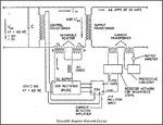
Saturable Reactor Current Control
The saturable reactor CCR consists of two saturable reactors,
main isolation transformer and control circuitry.
The AC reactance of the input saturable reactors is automatically
adjusted to regulate the load current.
This is a magnetic based design.

Ind_Reactor_Curr_Stab_01.jpg

Connect reactor coils to secondary circuit
 

Transformers are usually tested with output short circuit and reduced input voltage. A variable transformer is the basic tool needed for the measurement, besides voltage and current instruments.
 

Usually i check transformers at rated characteristics.

For example: under nominal load (20A) the Vo (Vout) should be Vo_n (Vout nominal) +/- 5%. 15' on 1h off x 3 cycles.

The Vin is regulated by a Variac.

The biggest problem is "follow" the nominal load due the heat dissipation of the variable resistance used as a dummy.


Tnx
 

Status
Not open for further replies.

Part and Inventory Search

Welcome to EDABoard.com

Sponsor

Back
Top