Continue to Site

Welcome to EDAboard.com

Welcome to our site! EDAboard.com is an international Electronics Discussion Forum focused on EDA software, circuits, schematics, books, theory, papers, asic, pld, 8051, DSP, Network, RF, Analog Design, PCB, Service Manuals... and a whole lot more! To participate you need to register. Registration is free. Click here to register now.

Eigenmode solver confusion

Status
Not open for further replies.

zam_nmn

Junior Member level 1
Joined
Jan 19, 2015
Messages
16
Helped
0
Reputation
0
Reaction score
0
Trophy points
1
Activity points
134
HI

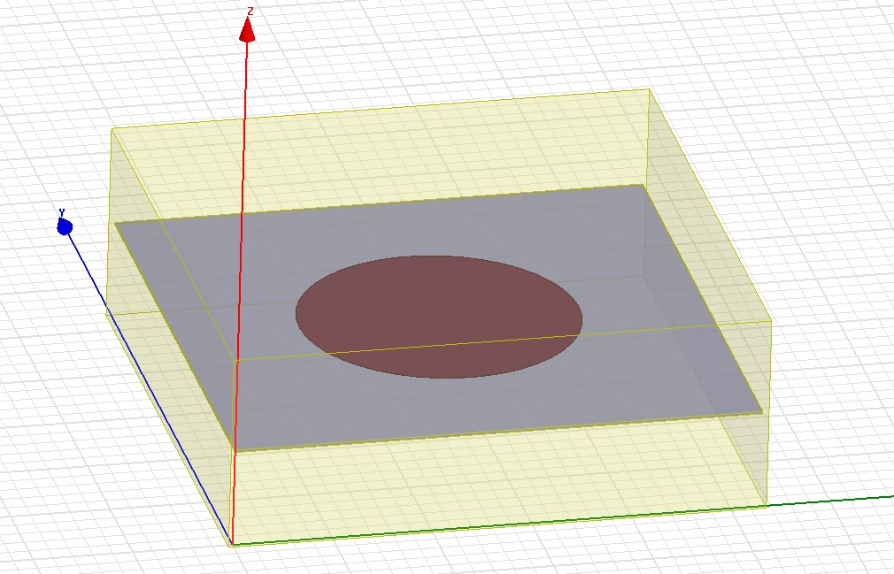
I am trying to design a dual mode sss filter at 1.8GHz and i'm using eigenmode solver to observe its resonance and q value.
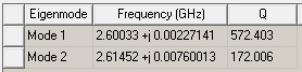
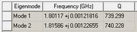
I need explaination on the results obtained, why does the resonance are very close to each other?
and how about the q value, is it to high?
 

Hi zam_nmn,

What are you expecting to get? You haven't provided enough information to comment any further. What setup/materials are you using? What are the field profiles of the different mode?
 

Hi PlanarMetamaterials,

This is my first time on Eigenmode solver and i don't really know what should i expect from it.
As for my case, i am using suspended stripline in my design with dielectric constant 2.33 and height 0.254mm.
To my knowledge, sss is a purely TEM material where the E and H field are transverse to the direction of propagation. I did set the enclosure as finite cond. so that it can evaluate the losses within.
I have a confusion with the results obtained, why the modes were so close to each other and what actually should i expect for a dual mode sss filter analysis? please guide me as i don't really understand about it.
 

Hi zam_nmn,

I'm afraid I don't know anything about that type of filter. If you post images if the fields though, I can tell you if they are correct for your setup or if there is an error somewhere.
 

Hi PlanarMetamaterials,

I am wondering why the resonance frequency and q value will change so much even though i only change the radius for a 0.001 point. let say the previous radius was 14.048mm which resonate somewhere around 1.8GHz with q value of 739. Then i changed the radius into 14.049mm and the resonance and q value greatly changed as per attached photo. i really want to know why this kind of small changes would greatly affect its resonance and q?
 

I would imagine this is a meshing issue, as you're right, it doesn't seem very plausible. Have you set up a seed mesh in the cavity? To do this, select the cavity and "Assign Mesh Operation". Set the length to be at least 1/20 of the cavity diameter.
 

Status
Not open for further replies.

Part and Inventory Search

Welcome to EDABoard.com

Sponsor

Back
Top