Continue to Site

Welcome to EDAboard.com

Welcome to our site! EDAboard.com is an international Electronics Discussion Forum focused on EDA software, circuits, schematics, books, theory, papers, asic, pld, 8051, DSP, Network, RF, Analog Design, PCB, Service Manuals... and a whole lot more! To participate you need to register. Registration is free. Click here to register now.

[SOLVED] EFT pulses supression

Status
Not open for further replies.

amit.kumar11

Member level 5
Joined
Jun 22, 2015
Messages
86
Helped
20
Reputation
40
Reaction score
19
Trophy points
8
Location
Bangalore
Activity points
471
Dear All,

I am using 3 phase input to my board. At input I have a MOV between phase to neutral and series fuse.

My board has to gone through IEC 61000 standard. We have tested surge i.e 61000-4-5 and it has passed but in EFT test 61000-4-4 our device is failing.

Thing is that, in surge test pulses will be in us(microsec) range so MOV is suppressing those pulses but in EFT it will be in ns(nanosec) and repetition rate is also more.

NOTE: Power supply section is working fine in this case. We have a I2C communication between ADC and controller. We have found that whenever we disable this communication by software, device works but whenever controller is trying to communicate with ADC its getting hang. We have probed I2C line in CRo and in these lines those EFT pulses are appearing.


Please suggest any device which I can put at input side to supress these pulses, so that it cant enter into device.

Amit
 

Have a look at gas discharge tubes http://www.digikey.com/product-search/en/circuit-protection/gas-discharge-tube-arresters-gdt/655426.

Proper layout is really important with any high-frequency or high-current signals. You are dealing with BOTH. Make sure that you are grounding these protection devices as near as possible to the end of the PCB where power is connected. This will prevent the very-high transient currents from flowing through your ground plane and creating very-fast spikes in the ground level where these sensitive components lie. Lastly, be sure to bypass the power supply with ceramic caps at each IC. This article is a good reference for bypassing guidelines. Bypass Capacitors – Why and How to Use Them?

What value pull-up resistors are you using on your I2C bus? If the value is too high, it increases susceptibility to interference.
 
What is the amplitude of the pulse, and what is the MOV rated? Is there a filter before or after the MOVs?

Without a detailed diagram, it's hard to say how the transient ends up on the I2C lines, or how that is causing the communication to "hang". Adding a few nF of capacitance to the I2C lines may solve that problem.
 
Pull up value used is 4.7k ohm

- - - Updated - - -

MOV is rated for 420V AC. I have the pi filter after MOV.
 

Hi,

Although I prefer the hardware solution, so that the bus never hangs, but this is not claimed by the IEC regulation.

A valid solution is to detect the "hanging" bus and initialize it a new. A pure software solution.


Klaus
 

Pull up value used is 4.7k ohm

- - - Updated - - -

MOV is rated for 420V AC. I have the pi filter after MOV.
And how is the surge being coupled in? Is it common mode (earth to hot/neutral) or differential (hot to neutral)? Or is it coupled on I/O?

MOVs probably aren't going to be terribly helpful for 50ns pulses, the input filter should be your primary defense against that. Could be that the chokes in your filter have too low of a self resonant frequency, allowing high frequency to pass through.
 
EFT
Up to 4kV
Energy <= 300mJ
Rep Rate 5kHz
rise time =5ns , PW50=50ns
Common source Arc noise.
Spectrum 5kHz ˜ 20MHz null + plus harmonics.

Gas tubes good clamp but far too slow (ionization time)
MOV's good clip but also slow. ( body capacitance)
CM filter , DM filter , Purpose : suppress impulse to tolerable levels and slow rise time.
Consider 40db rejection at 10~100MHz

Sometimes two CM filters are required for different bands.
You data cables may also need CM chokes and DM beads

What was the failure mode? functional?
THe energy applied is far below MOV ratings.

CMOS hangup is usually from SCR mode latchup, so TVS diodes + filter needed. Low loop area, or shielded cables with CM sleeve choke,& braid grounds are possible solutions.

Consider these ESD noise impulses as UHF/microwave impulses and examine radiated coupling and conducted coupling as well as common mode impedance at UHF

You can test at work using spark plug and coil with pulse gen. to generate noise.
 
Dear All,

Thanks for suggestion. I have used a common mode choke at input and a bidirectional TVS diode of 400V across MOV. Problem is solved.

Now I am worrying how to put that big choke in my board. Since I have tested with only one phase, I have to put TVS and choke for all three phase, which will be a big problem for me to accommodate in my board.

Please suggest some smaller size choke manufacturer. Choke details I will post, since it was a hand made choke and our team is mesuring all the parameters.
 

It's strongly advised that you don't put TVS diodes in parallel with the MOVs. Otherwise the diodes will blow before the MOVs even get to do anything. Typically MOVs are put on the mains side of the filter, and TVS diodes are put on the device side.

What sort of current are you drawing from the mains? Do you have a current carrying neutral? Three phase CM chokes can be bought off the shelf for low current levels.
 

I agree, this test is to simulate ESR or motor arcing on the line. for susceptibility not a lightning transient. Thus the interference is from high dv/dt ( e.g. 4kV/4ns= 1e12 V/s)

The problem may be capacitive coupling across SMPS transformer thus conducted common mode noise creating a differential voltage from unbalanced signals or radiated to signal lines >Vss,<Vdd causing SCR latchup on active CMOS drivers or receivers.

The solution is to shunt this LPF above 10MHz with series ferrite CM and DM beads to raise impedance then shunt with parallel RF caps ( <100pF) and use twisted pair and/or shielded TP.
 

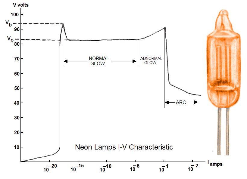
I have seen small Neon lamps being used in the input of circuits for cardiac monitoring equipment (ECG) to protect their electronic circuitry from the shots coming from the automated external defibrillators, which generate short duration high voltage discharges in the range of some KV's.
 

Gas tubes conduct heavily while Neon Tubes don't and represent maybe < 5 Ohms when arcing and is generally immune to arc with 50ns pulses due to 1 us or more ionization time.

I recall a Senior designer colleague using a gas tube across the line without fusing and it burned a hole in the board 10x bigger than the tube from the follow-on current, not from a direct hit, but induced spike near power line a few blocks away. No one else was affected.
Then I had to demonstrate it had SCR negative resistance characteristics in the lab before he believed me.

4926953500_1441385625.png
 
Yeah GDTs and avalanche-mode diodes must be used carefully, otherwise follow on current will be even worse than the surge you were trying to suppress. Normally to ensure this doesn't happen you need to know the approximate impedance of your AC source, which is never going to be well-defined.
 

is generally immune to arc with 50ns pulses due to 1 us or more ionization time

Indeed, but the neon lamp was just one of the first protection elements on the array. There were also high value resistors in series to the lamp, but I don't remember if there was also some capacitor in the net ( I guess it was there ), and finally a zenner diode close to the operational amplifier. Being the case, the RC time constant would not provide enough protection meanwhile ?
 

The test is performed with 0V differential and pulses applied common mode to the AC line.

Thus the solution is to raise Series CM impedance and lower Parallel CM impedance with appropriate CM hybrid chokes that work over this band of frequency content from the rise time to the pulse width. 20 to 40dB attenuation may be required. The coupling into unbalanced lines then creates a Differential Voltage which can exceed the device tolerance for impulse power. ( ESR of ESD protection is at least 15 Ohms. typ.) Thus one can analyze the fault from attenuation at 50MHz . THis can be tested also with a sig. gen at 50Mhz or a pulse gen AC coupled to source with X1 rated caps to measure attenuation from CM source to various points of potential failure with good measurement methods.
 
Dear All,

Thanks for all your suggestions. I have used a common mode choke between line and neutral and X caps at the i/p and o/p of the choke
and EFT has passed till +/- 3000 V.


Amit
 

Status
Not open for further replies.

Similar threads

Part and Inventory Search

Welcome to EDABoard.com

Sponsor

Back
Top