Continue to Site

Welcome to EDAboard.com

Welcome to our site! EDAboard.com is an international Electronics Discussion Forum focused on EDA software, circuits, schematics, books, theory, papers, asic, pld, 8051, DSP, Network, RF, Analog Design, PCB, Service Manuals... and a whole lot more! To participate you need to register. Registration is free. Click here to register now.

Effect of poles and dc gain of op amp to the close-loop AC response.

Status
Not open for further replies.

simbaliya

Member level 4
Joined
Feb 1, 2011
Messages
74
Helped
0
Reputation
0
Reaction score
0
Trophy points
1,286
Activity points
1,943
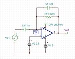
Hi, I have below circuit and I am trying to understand its close loop response.
TIA stage.jpg

Before simulation I try 2 method to calculate by hand its close-loop transfer function.

method1:
Vo1/(1/S*Cn1) = -Vo2/(RF1//(1/S*CF1))
Vo2/Vo1= -(RF*Cn1*S)/(1+RF1*CF1*S)
it shows there is one zero at zero frequency and one pole at 1/(2*pi*RF1*CF1), which means I should probably see sth like this
response1.jpg

method2:
calculate feedback factor beta first
beta = (1/S*Cn1)/[(1/S*Cn1)+(RF//(1/S*CF1))]
use a second order open loop transfer function for op amp
Ao = Adc/[(1+S/p1)(1+S/p2)]
calculate close-loop response Acl = Ao/(1+Ao*beta), and the result will be very complicated and different compared with method1.

Below is the simulation result, it shows there are 2 poles and 2 zero, which means method1(1 pole and 1 zero) is not accurate enough.
response2.jpg

Based on the simulation results, I believe method2 is more reliable. The DC gain and internal poles of op amp play a part to the close-loop response. But I have difficulty to solve pole and zero frequency of method2, it is too complicated, and I am not sure method2 is correct . I need some help here, thanks in advance.
 
Last edited:

Unfortunately, none of the bode plots can be related to the expectable small signal frequency characteristic of the circuit. According to a hand calculation, it should have a pole frequency of 4800 Hz and a high frequency gain of 20 dB. Same shape as the first curve, but different parameters.

Nothing is said about the OP properties, but the circuit isn't biased correctly (V2 should be e.g. 0.5*V1) and the amplifier apparently not working in it's linear range.
 

In hand calculation we are using single pole system and making many assumptions and approximations. For example, the transfer function of your system is:
\[\frac{V_{out}}{V_{in}}=-\frac{sC_1R_fK(s)}{1+R_f+K(s)+sR_f[C_f(K(s)+1)+C_1]}\]
In your example C_1 is one order of magnitude greater than C_f, its not too much but for us is still much greater, so when we divide nominator and denominator by K(s) we get:
\[\frac{V_{out}}{V_{in}} \approx -\frac{sC_1R_f}{1+sR_f(C_f+C_1/K_0)+s^2\frac{C_fR_F}{K_0 p_0}}\]
And usualy we do next assumptions, that the poles are good separated p_1<<p_2 so we approximating denominator of above formula as:
\[D(s)=1+s(\frac{1}{p_1}+\frac{1}{p_2})+\frac{s^2}{p_1p_2} \approx 1+\frac{s}{p_1}+\frac{s}{p_1p_2}\]
As the result we get two poles and one zero:
\[p_1=-[R_f(C_f+\frac{C_1}{K_0})]^{-1} \\
p_2=-\frac{p_0 (C_f+C_1/K_0}{C_f} \\
z = -(C_1 R_f)^{-1}\]

Of course this methods give You only real values of poles/zeros but is simply enough to analysis by hand.
 

Hi, do you mean that even without knowing op amp properties, you can still able to get the transfer function? But I changed the op amp dc gain, as well as pole position, result shows there will be huge difference.

- - - Updated - - -

Hi, thanks for all the explanation. However I do not get how you arrive at the first equation, and is K(s) the first order approximation of op amp?

Actually I made a mistake in method 2. I forgot that it is actually Vo2/Vx = Ao/(1+Ao*beta), and get Acl I need to do Vo2/Vo1 = (Vo2/Vx)*(Vx/Vo1).
TIA1.jpg

Can you explain how you calculate the close-loop gain from Vo1 to Vo2, besides, I found the equations you post is very easy to read, mind if I ask what software you are using to build these equations?
 

Attachments

  • TIA1.jpg
    TIA1.jpg
    43.6 KB · Views: 61

Yes K(s) is given by \[K(s)=K_0/(1+s/p_0)\] is single pole approximation of opamp.
The equations I build without any software. From definition of opamp, the output voltage is given by:
\[V_{out}=K(s)(V_+ - V_-)\] so I started from following equations:
\[(V_{in}-V_-)sC_1=(V_- -V_{out})y_f \\
V_- = -\frac{V_{out}}{K(s)} \\
y_f = \frac{1+sC_fR_f}{R_f}\]
 
It is obvious that you did not read the datasheet for the old LM301A opamp. It shows a minimum supply of 10V, its inputs must be at least 5V away from ground or the positive supply in your circuit and it usually needs an external compensation capacitor.
 

Yes K(s) is given by \[K(s)=K_0/(1+s/p_0)\] is single pole approximation of opamp.
The equations I build without any software. From definition of opamp, the output voltage is given by:
\[V_{out}=K(s)(V_+ - V_-)\] so I started from following equations:
\[(V_{in}-V_-)sC_1=(V_- -V_{out})y_f \\
V_- = -\frac{V_{out}}{K(s)} \\
y_f = \frac{1+sC_fR_f}{R_f}\]

Hi Dominilk, thank you for your help, I am now able to have the simplified transfer function on hand. However, when I use my designed parameters in the equation to solve pole and zero, I found that the assumption that p1 and p2 is far away is not true, this is my denominator equation 1+0.00000145s+0.000000000125s^2=0. But I think it is still ok for me, since I can solve this equation with software help. However I then found the solution is not real but complex values. What is the frequency value when the solution for pole is complex?
 

Status
Not open for further replies.

Similar threads

Part and Inventory Search

Welcome to EDABoard.com

Sponsor

Back
Top