Continue to Site

Welcome to EDAboard.com

Welcome to our site! EDAboard.com is an international Electronics Discussion Forum focused on EDA software, circuits, schematics, books, theory, papers, asic, pld, 8051, DSP, Network, RF, Analog Design, PCB, Service Manuals... and a whole lot more! To participate you need to register. Registration is free. Click here to register now.

Eagle Cad enlarge parts?

Status
Not open for further replies.
I don't understand what you mean. As you simple circuit takes 6 pages I think the parts are big enough! You can shrink the schematic to fit the page when you print it.

Keith
 

Symbols can be made any size you want them to be, but that would involve a lot of work. You would have to redo all of the types, e.g., resistor, capacitor, etc., using the make new device dialog.

A far easier method would be to reduce the amount of empty space and length of connecting wires. Eagle will then scale the whole schematic accordingly, and the symbols will be proportionately larger. If you attach a .sch file, I can at least get it started for you.

John
 

You can upload files to EDAboard directly.

I don't see why you want to make the parts bigger. Printed to A4 it looks fine. As John said, you can reduce dead space so it will scale larger when printing to a single sheet.

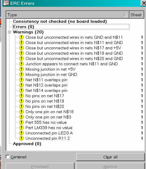
You do have an excessive number number of junctions on you schematic. They are only required where more than two wires join. Run the ERC for more errors such as two components on top of one another.

Keith.
 

Attachments

  • Tripwire Alarm21.pdf
    17.1 KB · Views: 63

@ElectroMan193
I have reduced the dead space, so the components will look larger. I noticed a few things. You seem to have several wires with multiple segments. The were a couple of resistors with a wire connecting both ends. And there were a couple of non-connects. I marked some of the things with "error," I went ahead and fixed R11-R12 +LED, there is an error at R9 with a wire connecting both ends, and I left most of the unconnected wires dangling so you could see them.

Here are some suggestions on using Eagle:
1) Learn to use the ESC key instead of trying to double click all wire ends. It does the same thing and many other useful things. Most important, it avoids unintentionally adding a dangling wire.
2) Never change grid in the course of drawing a schematic (or board). You can use the Alt key to get an alternate grid for parts placement and so fort, but be sure the main grid and alternate are a simple multiple of each other. That's why I redid the R11 group.
3) You don't need so many connections. It is better to put the wire to the component and then check to be sure it is connected. I do that by wiggling the component. ERC will also tell you what's not connected.

I put the sch file into a zip file so it would upload. Good luck.

John
 

Attachments

  • Tripwire Alarm21.zip
    32.3 KB · Views: 54

There are still a lot of errors on the schematic.

37_1306392580.gif


You DON'T need to use the ESC key when wiring. You should use NET not WIRE to do the wiring. Then the wire will end when you click on another pin or wire and it will add a junction if necessary. The use of WIRE for doing nets is not the nest way to connect NETS. If you do it that way you don't have to go wiggling components to see if they are connected.

Also, run the ERC!

Keith.
 
Good point about using Net. I still find the escape key useful when I get somewhere I don't want to be at other times.

And yes, there were a lot of errors. My focus was to compress the schematic, so I ignored most of them.

John
 

The use of WIRE instead of NET is a common mistake - caused by the names of the commands. WIRE sounds like the one to use! Unfortunately some of the layer names reflect Eagle's German origins as well such as "cream" instead of "paste".

I think the best this with the wiring is to completely remove it and start again. Turn off all layers except layer 91 (NETS), mark everything as a group and delete it. Then turn the other layers back on and the components will still be there. The start wiring with "NET". You shouldn't need to add junctions - they will be added where necessary.

Keith.
 

I am confused about your question please elaborate it.
 

Status
Not open for further replies.

Part and Inventory Search

Welcome to EDABoard.com

Sponsor

Back
Top