Continue to Site

Welcome to EDAboard.com

Welcome to our site! EDAboard.com is an international Electronics Discussion Forum focused on EDA software, circuits, schematics, books, theory, papers, asic, pld, 8051, DSP, Network, RF, Analog Design, PCB, Service Manuals... and a whole lot more! To participate you need to register. Registration is free. Click here to register now.

E-plane and H-plane radiation patterns

Status
Not open for further replies.

ashish.mw

Full Member level 2
Joined
Jul 18, 2011
Messages
121
Helped
15
Reputation
30
Reaction score
14
Trophy points
1,298
Location
India
Activity points
2,236
Dear all,
I am novice with HFSS. I have started working on antennas and have come across many terms like:
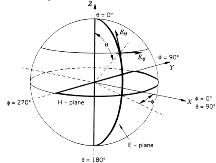
E-plane radiation pattern
H-plane radiation pattern
Elevation and radiation pattern
Cross and co polarization
I tried to follow Ludwig's work but surfing through the forums made my task a bit complex.
Now i wish to see each of the above curves via HFSS. Can anybody please take a bit of time to explain me the procedure of how to plot these curves. I shall be highly obliged. Please reply asap. Thanks in advance
 

You have to know a little about electro-magnetic theory. The E and H fields are at right angles to each other.

E and H plane is specifying polaration direction, referenced to E and H field directions, without knowing what is vertical and horizontal. Specifying vertical polarization is rather meaningless for a spacecraft flying between planets. Vertical relative to what?

A TV antenna with elements parallel to earth is usually called horizontally polarized or E plane parallel to earth surface. A whip antenna on a car is vertical polarized or E-field vertical to earth surface.

Most antennas have directivity, meaning energy is radiated more in a given direction. This is what gives antennas a gain relative to a theoretical spherical radiator (the sun is almost an isotrophic spherical radiator but it does radiate more at its equator then at its poles).

In theory, two antenna some distance apart must have same polarization to receive signals from each other. In real world there is some mutation of polarization, some in the antenna, some caused by the environment that creates some cross-polarization. In satellite communication, vertical and horizontal polarization is used, in part, to allow reuse of the same frequency spectrum without interference between the two. You can also have circular or eliptical polarization that is a mixture of right angle (quadrature) polarizations. Many commercial FM stations, and some UHF TV station are now using circular polarization to allow receiving antenna rods to be in random orientation. Signal reflections from billboards and water towers can cause reflected wave to change from its original polarization. You don't hold your mobile phone in the same orientation relative to the ground all the time.

Most antennas do not have the same directivity pattern in E plane and H plane. Spacecraft antennas are usually designed to make the E and H plane directivity patterns as identical as possible.

Sidelobes are secondary radiation directivity lobes created by a real antenna. They are generally an undesireable effect as they are spending some of the transmit power in directions you don't want it to go. In reception, the sidelobes can pick up unwanted signals.

Elevation is the the direction of the main antenna lobe relative to the horizon. For space communication, antenna noise temperature comes into play for ability to pickup signal. It is the result of blackbody radiation. Heat generates radiation. Earth is approximately 25 deg C, or 300 degrees Kelvin. A dish antenna pointing up in the air to pick up a satellite may only see a noise temperature of 10-35 degs K. This means there is lower background noise for the satellite dish looking at cold space and better signal to noise ratio. Remember sidelobes, if the same satellite dish looking at cold sky has sidelobes that look at hot earth then overall antenna noise temp is degraded, that degrades reception signal to noise ratio. As the dish is pointed closer to the horizon its noise temp goes up because it starts to see more of the hot earth.
 
Last edited:
Antenna Pattern Coordinates

 
  • Like
Reactions: mkk123

    mkk123

    Points: 2
    Helpful Answer Positive Rating
You have to know a little about electro-magnetic theory. The E and H fields are at right angles to each other.

E and H plane is specifying polaration direction, referenced to E and H field directions, without knowing what is vertical and horizontal. Specifying vertical polarization is rather meaningless for a spacecraft flying between planets. Vertical relative to what?

A TV antenna with elements parallel to earth is usually called horizontally polarized or E plane parallel to earth surface. A whip antenna on a car is vertical polarized or E-field vertical to earth surface.

Most antennas have directivity, meaning energy is radiated more in a given direction. This is what gives antennas a gain relative to a theoretical spherical radiator (the sun is almost an isotrophic spherical radiator but it does radiate more at its equator then at its poles).

In theory, two antenna some distance apart must have same polarization to receive signals from each other. In real world there is some mutation of polarization, some in the antenna, some caused by the environment that creates some cross-polarization. In satellite communication, vertical and horizontal polarization is used, in part, to allow reuse of the same frequency spectrum without interference between the two. You can also have circular or eliptical polarization that is a mixture of right angle (quadrature) polarizations. Many commercial FM stations, and some UHF TV station are now using circular polarization to allow receiving antenna rods to be in random orientation. Signal reflections from billboards and water towers can cause reflected wave to change from its original polarization. You don't hold your mobile phone in the same orientation relative to the ground all the time.

Most antennas do not have the same directivity pattern in E plane and H plane. Spacecraft antennas are usually designed to make the E and H plane directivity patterns as identical as possible.

Sidelobes are secondary radiation directivity lobes created by a real antenna. They are generally an undesireable effect as they are spending some of the transmit power in directions you don't want it to go. In reception, the sidelobes can pick up unwanted signals.

Elevation is the the direction of the main antenna lobe relative to the horizon. For space communication, antenna noise temperature comes into play for ability to pickup signal. It is the result of blackbody radiation. Heat generates radiation. Earth is approximately 25 deg C, or 300 degrees Kelvin. A dish antenna pointing up in the air to pick up a satellite may only see a noise temperature of 10-35 degs K. This means there is lower background noise for the satellite dish looking at cold space and better signal to noise ratio. Remember sidelobes, if the same satellite dish looking at cold sky has sidelobes that look at hot earth then overall antenna noise temp is degraded, that degrades reception signal to noise ratio. As the dish is pointed closer to the horizon its noise temp goes up because it starts to see more of the hot earth.


Thanks for your reply RCinFLA..the explanation is good. to much concern after having the clarity of all the mentioned terms, what my query says that i wish to know "how to achieve these plots via HFSS i.e the steps i need to follow". Please reply, thanks once again.

---------- Post added at 23:17 ---------- Previous post was at 23:07 ----------

Antenna Pattern Coordinates


Thanks for your reply.As far as i know these are just cylindrical coordinate system. Can you please elaborate what you wish to explain by this. Moreover please correct me wherever i am wrong. From Ludwig's 3rd definition of cross polarization:

Ecopol = Eθ cos φ − Eφ sin φ
Expol = Eθ sin φ + Eφ cos φ

where
when φ=0 degree, Ecopol, Expol represents E-plane components
and φ=90 degree, gives H-plane components
 

Status
Not open for further replies.

Part and Inventory Search

Welcome to EDABoard.com

Sponsor

Back
Top