Continue to Site

Welcome to EDAboard.com

Welcome to our site! EDAboard.com is an international Electronics Discussion Forum focused on EDA software, circuits, schematics, books, theory, papers, asic, pld, 8051, DSP, Network, RF, Analog Design, PCB, Service Manuals... and a whole lot more! To participate you need to register. Registration is free. Click here to register now.

Dual Output Flyback Converter with feedback regulation

Status
Not open for further replies.

Brandon Yau

Newbie level 6
Newbie level 6
Joined
Mar 9, 2015
Messages
12
Helped
0
Reputation
0
Reaction score
0
Trophy points
1
Visit site
Activity points
88
Hi everyone,

I have no idea about how to construct the PWM controller part in orcad Pspice, anyone knows the solution??

11020353_10153134961952082_2086099050_n.jpg
 

Hi

You can find a lot of documentation on this kind of circuitry on the internet.
You have basically to compare your feedback signal to a triangular waveform with a comparator, to generate the PWM.

Find examples for buck converters there, that you will have to adapt to your flyback dc-dc topology
https://www.ee.bgu.ac.il/~pel/presentation/PET06/PET06.pdf

Good luck
Thanks for the link!

However, something keeps on confusing me.
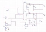
Here is my Orcad design of the circuit.

**broken link removed**

1. I do not have a voltage source in the primary side, how can I generate a duty cycle for the secondary circuit to work before the optocoupler sends back the error signal current to the primary side and adjust the duty ratio of the switch? A zero duty cycle at the beginning cannot generate any output voltage in the secondary side, how would any error be generated and do the feedback?


2. A current to voltage converter is applied for the current signal current to be converted to voltage and drive the switch. Is is correctly built?
 

Im sorry for the invalid attachment.

Here is the photo.

1.JPG

Can anyone teach me how to construct the PWM controller in the first post without any MCUs?
The PWM controller should contain a lot of parts, but I have no idea in it...

The PWM controller should have the following functions,
1. Convert the feedback signal current into an error voltage
2. The error voltage drives the switch

Is it correct?
 

Can anyone teach me how to construct the PWM controller in the first post without any MCUs?

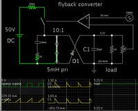
Here is a simulation illustrating the concept of a flyback, with basic control technique.

It does not self-regulate. Nevertheless it's a start on the path to a design like your project.


The control device is an op amp (or comparator).

A feedback signal is taken from the output stage. The comparator changes state at the point where the volt level crosses a sawtooth waveform.

The potentiometer can be adjusted to provide a different feedback voltage. This in turn alters the duty cycle.
 
Status
Not open for further replies.

Similar threads

Part and Inventory Search

Welcome to EDABoard.com

Sponsor

Back
Top