Continue to Site

Welcome to EDAboard.com

Welcome to our site! EDAboard.com is an international Electronics Discussion Forum focused on EDA software, circuits, schematics, books, theory, papers, asic, pld, 8051, DSP, Network, RF, Analog Design, PCB, Service Manuals... and a whole lot more! To participate you need to register. Registration is free. Click here to register now.

[SOLVED] dspic33f ADC Multiple Channels Help

Status
Not open for further replies.

bubble_d

Junior Member level 3
Joined
Sep 12, 2012
Messages
25
Helped
0
Reputation
0
Reaction score
0
Trophy points
1,281
Activity points
1,483
Hi Everyone,

So I need help Implementing a 4 channel ADC where I read 4 voltages.

So far I have one ADC working, but I dont really understand how I would do multiple adc sampling.

When I initialize my ADC, do I just need to change my AD1PCFGH (Analog inputs) to select my four input pins?

Also I am unsure how to read the voltages of three channels, do i need four ADC read functions where I return 4 separate buffers which will give me my voltage?

Here is what I have for now: (ADC.h)

Code:
void initADC( int amask)
{
    AD1PCFGH = amask;      // select analog input pins
    AD1CON1 = 0x00E0;     // data output format-integer, auto convert after end of sampling.12bit Operation mode. No need to include a delay loop to provide time for completion of sampling
    AD1CSSL = 0;          // no scanning required
    AD1CON3 = 0x1FFF ;     // Use internal clock, max sample time avail is 31Tad, conversion time Tad = 128*Tcy = 128*(2/Fosc) = 256/8MHz = 32us which is > (required)75ns ); 31 Tad = 31*32us = 992us is the sample time. About 100samples/sec
    //Possibly 1FFFF Check Both
	AD1CON2 = 0;          // use MUXA, AVss and AVdd are used as Vref+/-
    AD1CON1bits.ADON = 1; // turn on the ADC
} //initADC


int readADC1( int ch)
{
    AD1CHS0  = ch;               // select analog input channel
    ADC1BUF0 = 0x0000;   		// Reset Buffer
    AD1CON1bits.SAMP = 1;       // start sampling, automatic conversion will follow at end of sampling   
    while (!AD1CON1bits.DONE);  // wait to complete the conversion. DONE will be set as soon as conversion ends
    return ADC1BUF0;            // read the conversion result
} // readADC


//Forth Module is used for now because it is easy to access in hardware setup
int readADC4( int ch)
{
    AD1CHS0  = ch;               // select analog input channel
    ADC1BUF0 = 0x0000;   		// Reset Buffer
    AD1CON1bits.SAMP = 1;       // start sampling, automatic conversion will follow at end of sampling   
    while (!AD1CON1bits.DONE);  // wait to complete the conversion. DONE will be set as soon as conversion ends
    return ADC1BUF0;            // read the conversion result
} // readADC

Obviously I am getting errors that are telling me ADC1BUF1 is undeclared.


Can anyone help me out? Or even lead me in the right direction with an example?

Thank you.

[EDIT] I just realized there is no ADC1BUF0 :p. I guess Im looking into this all wrong... I set it to ADC1BUF0 and the program ran but I was getting the max voltages (I.e the voltages added together but it clips at 3.3) How do I do this!~!!
 
Last edited:

IN 10-bit mode the ADC can sample 4 channels simultaneously, however in 12-bit mode you have to sample and convert them one-by-one. The following code should allow you to convert any single-channel:
Code:
int readADC(int channel)
{
	AD1CHS0bits.CH0SA = channel;			// Select the channel to convert
	IFS0bits.AD1IF = 0; 					// Clear ADC interrupt flag
	AD1CON1bits.DONE=0;						// Clear Done Flag
	AD1CON1bits.SAMP=1; 					// Start sampling 

	while(IFS0bits.AD1IF == 0);				// Wait for conversion complete

	AD1CON1bits.ASAM = 0; 					// Then stop sample/convert...
	return(ADC1BUF0);
}
 

I applied the code you gave me and then sampled two channels and I got readings but both the variables I set to hold the ADC1BUF0 values given by the ADC seem to add together instead of seperating the two values.

I.E I have 3.7 Volts entering RB3 and(I use a voltage divider to be able to hangle voltages >3.3) and 4.1 Volts entering RB8, Although when I show either voltages I get 6.6V (I.E max 3.3 V due to multiplier to cancel out voltage divider). I would expect it to show 3.7 V for one variable and 4.1 V for the other. Any Ideas?

This is my Main Code:

Code:
#include <stdio.h>
#include <stdlib.h>
#include "p33FJ256GP710a.h"
#include "lcd.h"
#include "ADC.h"
#include "delay.h"

//ADC CHANNELS
// Each channel was selected such that a ground pin is right next to the input
// pin while the pin needed to be a ADC pin
#define Moduleinit 0x0108
#define B1ADC 3 //AN3 Selected for 'Battery Module' 1
#define B2ADC 0 //AN0 Selected for 'Battery Module' 2
#define B3ADC 1 //AN1 Selected for 'Battery Module' 3
#define B4ADC 8 //AN8 Selected for 'Battery Module' 4
// Buttons
#define SW1 PORTDbits.RD6
#define SW2 PORTDbits.RD7
#define SW4 PORTDbits.RD13
//LEDS
#define LED1 LATAbits.LATA0
// I will start with A single battery module then once this
// works will I continue with all the modules.

//***************************************************************

_FOSC(OSCIOFNC_ON & FCKSM_CSDCMD & POSCMD_NONE);	//Oscillator Configuration
_FOSCSEL(FNOSC_FRC);								//Oscillator Selection
_FWDT(FWDTEN_OFF);									//Turn off WatchDog Timer
_FGS(GCP_OFF);										//Turn off code protect
_FPOR( FPWRT_PWR1 );								//Turn off power up timer

void Update_LCD( void );
double voltage1;
double voltage2;
const char mytext[] = "hello";
const char mytext1[] = "EDP 2013";
const char mytext2[] = "shitz";
const char mytext3[] = "Holla";
const char mytext4[] = "fuck you";
char result [24];

int main(void)
{

	//Variables For Switches
	int	SW1Pressed=0;
	int	SW2Pressed=0;
	int	SW4Pressed=0;
	double v1 =0;
	double v2=0;

	TRISA = 0x007E;			//Make all PORTs all outputs
	/* Initialize LCD Display */
	Init_LCD();
	/* Welcome message */
	home_clr();
	puts_lcd( (char*) &mytext[0] );
	line_2();
	puts_lcd("BITCHES");
	
	initADC(Moduleinit);

	TRISB = 0x0108; //Sets RB3/AN3 as input since AN3 is being used as analog Input
	

	while(1)
	{				// delay 200ms


		if(SW1Pressed==1){
		
		home_clr();
		
		v1 = readADC(B1ADC); //Read ADC
		voltage1 = (v1/1024)*6.6;


		sprintf(result,"Voltage: %0.2f",voltage1);
		puts_lcd(&result);
		Delay(50);
}else if(SW2Pressed==1){

	home_clr();
		
		v2 = readADC(B4ADC); //Read ADC
		voltage2 = (v2/1024)*6.6;


		sprintf(result,"Voltage: %0.2f",voltage2);
		puts_lcd(&result);
		Delay(50);

}

		if(!SW1){
		
		SW1Pressed=1;
		SW2Pressed=0;
		SW4Pressed=0;
		

		}else if (!SW2) {
		
			SW1Pressed=0;
			SW2Pressed=1;
			SW4Pressed=0;
		

		}else if (!SW4) {

			home_clr();
		//	Delay(50);
			puts_lcd(&mytext3);
		
		}

		
}
}
 

What do you get if you ground one of the pins? What do you get if you ground both of the pins?
 

They are both grounded initially and when I only ground one of them, The grounded one Gives me the correct voltage, the other one gives me...0.72 V but it deviates a lot.
 

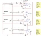
The actual hardware design I am using isnt complete, So I temporarily connected my 3.7 V cell to a potentiometer with ground connected to explorer 16 ground, I also connected another module directly to the ADC pin and the ground pin to the ground pin as well. I will send you my actual schematic when I get home.

Thanks.

Oh and I also included a voltage divider so I can handle the 3.7 V which is >3.3v Max


EDIT [Here is my Schematic]
Design.jpg
 
Last edited:

The grounded one Gives me the correct voltage, the other one gives me...0.72 V but it deviates a lot.
This pin should give "0" if connected to ground. I am attching one of the demo code chunk that i wrote for dsPIC33FJ64MC506A. Have a look and change the extention of the file.
 

Attachments

  • ANALOG.h.txt
    1.6 KB · Views: 183
  • ANALOG.c.txt
    1.8 KB · Views: 135

Once I fixed some errors I got it working :)

Also my circuit was giving me errors. I plugged in 3 batteries directly and I get 3 different voltages

Thank you everyone
 

Status
Not open for further replies.

Similar threads

Part and Inventory Search

Welcome to EDABoard.com

Sponsor

Back
Top