Continue to Site

Welcome to EDAboard.com

Welcome to our site! EDAboard.com is an international Electronics Discussion Forum focused on EDA software, circuits, schematics, books, theory, papers, asic, pld, 8051, DSP, Network, RF, Analog Design, PCB, Service Manuals... and a whole lot more! To participate you need to register. Registration is free. Click here to register now.

[SOLVED] dspic33 programming problem

Status
Not open for further replies.

csstudent

Newbie level 6
Joined
Apr 28, 2015
Messages
11
Helped
0
Reputation
0
Reaction score
0
Trophy points
1
Activity points
101
Hello edaboard,

I am working on a project, and for that project I have to program a dspic33ep128mc206 microcontroller from microchip. This is a link to the specific chip.
https://www.microchip.com/wwwproducts/Devices.aspx?product=DSPIC33EP128MC206

The data sheet for the dspic is at the bottom of the page.

We have connected all the Vdd, Avdd, Vss, and Avss pins correctly. We have place a 10uF tantalum capacitor at the Vcap pin, we have .1uF decoupling capacitors between each Vss and Vdd pin, and we've tried an assortment of resistors for the pullup resistor on the MCLR pin ranging from 4.7k to 10k ohms (the recommended starting point). We have also made an effort to place everything as close to the microcontroller as possible, since the datasheet specificies that the capacitors need to be as close as possible to the chip.

When are using external power (3.3 V) when trying to program the pic and are using a pickit3 to program. We are also using a breadboard and aren't doing any SMT or through-hole soldering.

The problem when we try to program the PIC is that there is too much current draw when supplying 3.3V to the Vdd lines (on the order of 1 Amp). We burnt out a chip once doing that (it made a smell and got crazy hot) and so we've been trying to do it again, but this time limiting the current to about .1A. However, when we do this, we only are able to supply 1.1V to the pic since our power supply is limiting the current. We have done a continuity test and get about 518 ohms of resistance (so no shorts), however for some reason there is still too much current being drawn. I am unsure how to fix this. Any advice would be helpful. Also if anybody has any general tips for how to program a pic that would be great, specifically any pitfalls that many people fall into when trying to hook everything up, but aren't obvious pitfalls.

I've been looking through the microchip forums to look for people with similar problems and I think I've done everything that was given to those people for advice.

Thanks for any help you can give.
 

Bump:

We have been playing with everything some more and we've found out that we can supply 3.3V at .2 Amps on Avdd and Avss, but for the Vdd & Vss pins, we can only supply 1.1 V at .2 A. If we go higher on those pins, we might destroy the chip. Is this normal behavior?
 

The problem when we try to program the PIC is that there is too much current draw when supplying 3.3V to the Vdd lines (on the order of 1 Amp). We burnt out a chip once doing that (it made a smell and got crazy hot) and so we've been trying to do it again, but this time limiting the current to about .1A. However, when we do this, we only are able to supply 1.1V to the pic since our power supply is limiting the current. We have done a continuity test and get about 518 ohms of resistance (so no shorts), however for some reason there is still too much current being drawn. I am unsure how to fix this. Any advice would be helpful. Also if anybody has any general tips for how to program a pic that would be great, specifically any pitfalls that many people fall into when trying to hook everything up, but aren't obvious pitfalls.

If the dsPIC is drawing 1A at 3.3v, there is definitely a wiring/connection issue, possibly a reversed polarity.

Have you connected all four Vdd, three Vss, AVdd, AVss and Vcap pins to there proper voltage levels?

Draw a schematic of the minimum connections required, comparing it against the datasheet and then double check your connections, also post this schematic once you have accomplished this task.

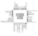
dsPIC33EP128MC206_506PinOut.JPG

Note: there is a high probability you have already damaged the current dsPIC.


BigDog

- - - Updated - - -

Is this normal behavior?

No, not hardly. Most likely the current dsPIC is already damaged.
 

I don't think we've burnt out this chip. We've been current limiting the circuit the entire time and it has never gone above .3A, which is the maximum operating current at normal temperatures for this pic.

sheet2.png

This the minimum required connections, specified by the datasheet.
Screen shot 2015-04-27 at 9.11.04 PM.png

This is a schematic of our circuit (its a bit messy, there are many wires). There are .1uF capacitors between all the Vss/Vdds (and Avdd/Avss). We have also used the correct Vcap capacitor. We are not using the capacitor at MCLR, as it was not recommended when programming, and are also not using the 100 ohm resistor (or the R1 resistor in the recommended picture) because the Pickit3 documentation excludes it when programming.
 

The connection from the Vcap capacitor is connected to what? It runs off the page, as does the LED connection to its left.
 

halp.png
I redrew the schematic to more accurately reflect what we are bread boarding. Vcap is going to ground and we aren't using the led. Also, we aren't using a battery, but an external power supply (the image says a battery however). Also, we aren't inputting 3.3V, usually its around .9V-1.2V because we are current limited in the .1A to .3A range.
 

Attachments

  • halp.png
    halp.png
    106.1 KB · Views: 105

I don't know if the last post went through, so here is the new, easier to read schematic that reflects what we are actually breadboarding.

halp.png

For MCLR, we have tried multiple configurations. One without any of the resistors and just plugging the MCLR line straight into the pickit3. Apparently the pickit will automatically switch between 5v and GND, which means that we don't need the pullup resistor. We have also tried a configuration with the pullup resistor, but not with the small 100 ohm resistor, since the pin is 5v tolerant and we won't over volt it (i hope).
 

If you remove the PICkit 3 connections from the device, does the situation still persist?

If removing the PICkit 3 connections doesn't remedy the situation, remove each of the Vdd and AVdd connections one by one, if that doesn't remedy the situation replace them and do the same with the Vss and AVdd connections, carefully monitoring the power supply.

Also remove all connections to Vdd, Vss, AVdd and AVss and check for shorts with a multimeter.

BigDog
 

Yes, the problem still persists. I am not at the lab at the moment (we tried without the pickit3 earlier, and we have two pickit3's and tried both), but we did the opposite of you suggestion, where we started with no Vdd/Vss pins connected, provided power (.2A max current) and then slowly added Vdd/Vss connections to see what happened.

The problem didn't change when we were adding more Vdd/Vss pins. The voltage was around 1.1-1.2V at .2A whether there were 1 or 3 Vss/Vdd pins. We tried doing Avdd/Avss in isolation and found that at about .15-.2A we could supply a voltage of about 3.2-3.3V to the pic. When we connected a single Vss/Vdd pair and and single Avdd/Avss pair, the system went back to supply 1.1-1.2V and drawing .2A.
 

Then most likely there is a short between the Vdd and Vss either internally or externally.

Also remove all connections to Vdd, Vss, AVdd and AVss and check for shorts with a multimeter.

How is the device mounted, on a breakout board?


BigDog
 

The device is mounted on a breakout board, we had a company do the soldering for us, since the pic is a small QFN package. When you say check for shorts, do you mean to check for resistance between each pair of Vdd/Vss pins?
 

TWhen you say check for shorts, do you mean to check for resistance between each pair of Vdd/Vss pins?

Yes, exactly. Look for a low resistance path between them, from your description it is the most probably cause of the large current measurements.

With the bare minimum connections shown in your schematics, the normal current draw should be considerably less 100mA at 3.3V.

The specification from the datasheet: 0.6 mA/MHz Dynamic Current (typical).

BigDog

Yes, remove all your ceramic capacitors (don't reuse any of the capacitors from the previous dsPIC33 chip that burnt), remove any other components, even PICKITs.

Test 1:
Take 1 pair of Vdd-Vss and do the following.
Current limit at 100mA.
Put voltage to zero.
Ramp up the voltage from 0-3.3V.
If the current wants to go above 100mA or voltage is stuck below 3.3V, then go to test .

Test 2:
remove the dspic from breadboard, check for resistance and continuity between that particular VDD-VSS you tested in Test 1.

Please post the result of test 1 and test 2.
 

These are the resistances we got between each of the pairs of Vdd/Vss (with correct polarity at each)

pins 9 & 10 (Vss/Vdd) = .1 mOhms
pins 19 & 20 (Avdd/Avss) = 47 kOhms
pins 25 & 26 (Vss/Vdd) = 48 kOhms
pins 38 & 41 (Vdd/Vss) = 104 mOhms
pins 56 & 57 (Vcap with no capacitor, Vdd) = 47 mOhms

We did what you said, where we ramp up the voltage with a single pair of Vdd/Vss pins (with new capacitors) and weren't able to bring the voltage higher than around 1 Volt with .1A

Here are the results of the continuity test for each pin pair (this is what the multimeter said)
pins 9 & 10 (Vss/Vdd) = 737 ohms
pins 19 & 20 (Avdd/Avss) = 1000 ohms
pins 25 & 26 (Vss/Vdd) = 737 ohms
pins 38 & 41 (Vdd/Vss) = Open
pins 56 & 57 (Vcap with no capacitor, Vdd) = Open

which of these sets of measurements is with the dsPIC breakout board removed from the breadboard?
 

All of them.

- - - Updated - - -

We think we figured out what was going wrong. This going to be incredibly dumb, but we contacted the guys who soldered the pic to the board for us and we realized that there were extra pins we weren't connecting. The breakboard has extra pins for the ground plate on the back of the PIC (i guess all qfn packages have this back plate?). So we were off by one on all our connections and didn't have the back plates connected to ground. We are going to try it out soon. Hopefully we didn't mess up the chip. Can't believe we didn't notice this :(
 

So we were off by one on all our connections and didn't have the back plates connected to ground. We are going to try it out soon. Hopefully we didn't mess up the chip. Can't believe we didn't notice this :(

Typically, the most obvious answers are the most probable. There were only a few possible causes of such a relatively large current draw and it appears you may have found one.

BigDog
 

We programmed it!!! The problem was exactly that, we weren't connecting the backplate ground plane. thanks for your help. If we didn't do what you guys said, we might've blown up another pic in the process of debugging.
 

Status
Not open for further replies.

Similar threads

Part and Inventory Search

Welcome to EDABoard.com

Sponsor

Back
Top