Continue to Site

Welcome to EDAboard.com

Welcome to our site! EDAboard.com is an international Electronics Discussion Forum focused on EDA software, circuits, schematics, books, theory, papers, asic, pld, 8051, DSP, Network, RF, Analog Design, PCB, Service Manuals... and a whole lot more! To participate you need to register. Registration is free. Click here to register now.

[PIC] ds1307 slows with 7 segment display

Status
Not open for further replies.

mayasunny

Member level 3
Joined
Mar 21, 2019
Messages
56
Helped
0
Reputation
0
Reaction score
0
Trophy points
6
Activity points
481
Hello all,
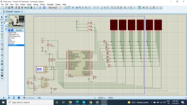
I am currently working with developing Digital clock. I'm using PIC18F4550, DS1307 RTC, 6 seven segment display for displaying clock in HH.MM.SS format.
While reading the clock, I'm getting approximately 10 sec of delay for each second. I don't know where I'm going wrong. Below are my specifications
1. pic18f4550 micro controller
2. Ds1307 RTC with 32.76KHz, 3v battery
3. 1-digit Common cathode 7-segment displays ( using multiplexing concept)

If I mention about 500ms delay after every read, it shows the proper time but 7-Segment display is flickering continuously.
I testing the code with proteus software.
 

Solution
It seems appropriate to use the RTC for time display. The accuracy of processor clock usually can't keep up with the RTC. And it's much simpler to keep the time over power loss. Even if you prefer a software clock, you'll synchronize it to the RTC from time-to-time.
thanks for your replay Mr.Brain
Code:
#include <xc.h>
#include <stdio.h>
#include <string.h>
#include <ctype.h>
#include "configbits.h"
#include "i2c.h"                                // This header file includes I2C.c file which is used to interface the I2C
#include "uart.h"                                // This header file includes uart.c file which is used to interface the UART for serial communication
#include "segment.h"
#include "lcd.h"
#define _XTAL_FREQ 20000000
#define I2C_SPEED 100000 // kbps
//Function Declarations

// Define RTC device address
#define DS1307_Add_write 0xD0
#define DS1307_Add_read 0xD1
#define switch1 PORTCbits.RC0
#define switch2 PORTCbits.RC1
#define switch3 PORTCbits.RC2

int sec,min,hour;
int Day,Date,Month,Year;
int i;
char secs[10],mins[10],hours[10];
char Clock_type = 0x06;                                    
char AM_PM = 0x05;
int H_value,M_value,S_value;
int upd_hour,upd_min,upd_sec;
int status,status1,status2;


char BCDtoDecimal (char val)
{
    char res;
    res = (val & 0x0F) + ((val & 0xF0)>>4)*10;
    return res;
}

char Dec2BCD(char val)
{
    char res;
    res = (val/10) << 4;
    res = res | (val % 10);
    return res;
}

void RTC_Clock_Write(char sec1, char min1, char hour1, char AM_PM)                    // function for clock
{
    I2C_Start();
    I2C_Write(0xD0);
    I2C_Write(0x00);
   // I2C_Write(0x80);    //CH = 1 Stop oscillator
    I2C_Write(Dec2BCD(sec1));
    I2C_Write(Dec2BCD(min1));    //Minute
    I2C_Write(Dec2BCD(hour1)); //Hour

    I2C_Stop();        //Stop the I2C Protocol
    __delay_ms(20);

}


void RTC_Read_Clock(char read_clock_address)
{
    I2C_Start();
    I2C_Write(DS1307_Add_write);
    I2C_Write(Dec2BCD(read_clock_address));
    I2C_ReStart();
    I2C_Write(DS1307_Add_read);
    sec = I2C_Read_Byte();                                                             //read data and send ack for continuous reading
    I2C_Send_ACK();
    min = I2C_Read_Byte();                                                             //read data and send ack for continuous reading
    I2C_Send_ACK();
    hour= I2C_Read_Byte();                                                             //read data and send nack for indicating stop reading
    I2C_Send_NACK();
}

void Read_RTCclock(void)
{
    RTC_Read_Clock(0);                                                    //gives second,minute and hour
    I2C_Stop();
    __delay_ms(10);
    if(hour & (1<<Clock_type)){                                                 // check clock is 12hr or 24hr
        hour = hour & (0x1f);
        hour = BCDtoDecimal(hour);
        min = BCDtoDecimal(min);
        sec = BCDtoDecimal(sec);
        Segment_Disp(hour,min,sec);
    }
    else{
        hour = hour & (0x3f);
        hour = BCDtoDecimal(hour);
        min = BCDtoDecimal(min);
        sec = BCDtoDecimal(sec);//__delay_ms(250);
        Segment_Disp(hour,min,sec);
    }
  
}   


void main()
{
    ADCON1 = 0X0F;
    segment_Init();
    int count = 0;
    InitI2C();
    TRISB0 = 1;
    TRISB1= 1;
    TRISC0 = 1;
    TRISC1 = 1;
    TRISC2 = 1;
    PORTC = 0X00;                                                                //set frequency to 8 MHz

    while(1)
    {
        Read_RTCclock();
    }
}
--- Updated ---

Here is the schematic
 

Attachments

  • Final_Clock.zip
    18.8 KB · Views: 113
Last edited by a moderator:

Hi,
using multiplexing concept
I can´t find any display multiplexing in your code.

Also I can´t open your attachment. Please upload the schematic as PNG or as PDF.

***
Generally the whole code is a waste of processing power.
I´d use a software clock, calibrate the SW clock only every couple of hours.
You may even use the SQW/OUT of the RTC .. so the software clock is sync´d to the HW RTC.

I´d say a software clock needs about 0.001% of processing power. (My guess: 10us per second)
In other words: your code consumes maybe 100,000 times the processing power.

Klaus
 

It seems appropriate to use the RTC for time display. The accuracy of processor clock usually can't keep up with the RTC. And it's much simpler to keep the time over power loss. Even if you prefer a software clock, you'll synchronize it to the RTC from time-to-time.
 

Solution
Mr.KlausST, below is a 7-segment multiplexing code
[ code ]
Code:
#include <xc.h>
#include "configbits.h"
#include "segment.h"
#define _XTAL_FREQ 20000000                                                 //define crystal frequency to 20MHz
#define control1 PORTBbits.RB2
#define control2 PORTBbits.RB3
#define control3 PORTBbits.RB4
#define control4 PORTBbits.RB5
#define control5 PORTBbits.RB6
#define control6 PORTBbits.RB7
char binary_pattern[]={0x3F,0x06,0x5B,0x4F,0x66,0x6D,0x7D,0x07,0x7F,0x6F};


void segment_Init(void)
{
    TRISD = 0X00;                                                              // initialize PORTD pins to active low
    TRISB2 = 0;
    TRISB3 = 0;
    TRISB4 = 0;
    TRISB5 = 0;
  //    // TRISC = 0X00;
    TRISB6 = 0;
    TRISB7 = 0;
    ADCON1 = 0X0F;                                                              // To Make PORTB pins as Digital I/O
    control1 = 1;                                                               // TurnOff all 6 Segments
    control2 = 1;
    control3 = 1;
    control4 = 1;
    control5 = 1;
    control6 = 1;


}
void Segment_Disp(int value1, int value2, int value3)
{
   // PORTD = 0X80;
    unsigned int a,b,c,d,e,f;
    a = value1 / 10;                                                           
    b = value1%10;                                                         
    c = value2/10;                                                             
    d = value2%10;                                                             
    e = value3 / 10;                                                         
    f = value3 % 10;                                                           
    PORTD=binary_pattern[a];             
    control1=0;                                                     
    __delay_ms(3);
    control1=1;                                                               
    PORTD=binary_pattern[b] | 0x80;                     
    control2=0;                                                               
    __delay_ms(3);
    control2=1;                                                     
    PORTD=binary_pattern[c];
    control3 = 0;                                                           
    __delay_ms(3);
    control3=1;
    PORTD=binary_pattern[d] | 0x80;                       
    control4 = 0;                                                               
    __delay_ms(3);
    control4=1;
    PORTD=binary_pattern[e];                                               
    control5 = 0;                                                         
    __delay_ms(3);
    control5 = 1;                                                           
    PORTD=binary_pattern[f];                                                 
    control6 = 0;                                                         
    __delay_ms(3);
    control6 = 1;                                                       
 
}
[ /code ]
 

Attachments

  • Screenshot (2).png
    Screenshot (2).png
    167.9 KB · Views: 186

Hi,

your display_mux routine takes more than 18ms.
then there is another 10ms wait in Read_RTCclock (I see no use of it)
so one loop takes mor then 28ms. Let´s say 30ms.

You know the clock changes once per 1000ms.
So you read the RTC 33 times without change in time.
then you calculate all the display data 33 times per second... without change in time..

You are free to do so.

But:
You could wire the SQR/OUT to the microcontroller´s port.
Every time there is a rising edge at this port read the RTC (could be done in main loop context)
after reading the RTC calculate all values .. and store the display data (port D) in an array.
(Once per second)

During INIT set up a timer for about 3ms (no need to be accurate). Just for the display_mux.
In this ISR just update the digit counter (0...5) and output the array data to portD.

Don´t use any _delay_ms at all.

Then there is plenty of processsing power for ALARM, reading push buttons, ... or to enter SLEEP mode.
No display flicker ... independent of processor load.

Klaus
 

    mayasunny

    Points: 2
    Helpful Answer Positive Rating
You could wire the SQR/OUT to the microcontroller´s port.
Every time there is a rising edge at this port read the RTC (could be done in main loop context)
after reading the RTC calculate all values .. and store the display data (port D) in an array.
(Once per second)


Klaus
Thanks for your response, can explain a bit more in detail about this
 

I would configure the DS1307 to produce 1Hz output, connect it to the PIC INT pin so it interrupts once a second. Read the DS1307 once at start up and increment the time in software. That way you get the same accuracy as the DS1307 but only have to read it once. For the display multiplexing use an internal timer to change from one display to the next, that way you get reliable fixed speed (=constant brightness) display updating.

Brian.
 

    mayasunny

    Points: 2
    Helpful Answer Positive Rating
Hi,

What is unclear?
The RTC has an SQW/OUT .... just connect it with a PIC port pin, or a PIC interrupt input pin.

When programmed to output 1Hz, then it gives a pulse every second.

Klaus
 

    mayasunny

    Points: 2
    Helpful Answer Positive Rating
@mayasunny,

It seems to me that this homework assignment is beyond what you have so far been taught.

Here is a complete, builds with MPLAB v5.50 and XC8 v2.32, demo application:
C:
/*
 * File:   main.c
 * Author: dan1138
 * Compiler: XC8 V2.32
 * IDE: MPLABX v5.50
 *
 * Created on July 26, 2021, 3:26 PM
 *
 *                       PIC18F4550
 *               +----------:_:----------+
 *    VPP  ->  1 : RE3/MCLR/VPP  PGD/RB7 : 40 <> DIGIT0/PGD
 *         <>  2 : RA0/AN0       PGC/RB6 : 39 <> DIGIT1/PGC
 *         <>  3 : RA1/AN1       PGM/RB5 : 38 <> DIGIT2
 *         <>  4 : RA2/AN2      AN11/RB4 : 37 <> DIGIT3
 *         <>  5 : RA3/AN3       AN9/RB3 : 36 <> DIGIT4
 *         <>  6 : RA4      INT2/AN8/RB2 : 35 <> DIGIT5
 *         <>  7 : RA5/AN4 INT1/AN10/RB1 : 34 <>
 *         <>  8 : RE0/AN5 INT0/AN12/RB0 : 33 <>
 *         <>  9 : RE1/AN6           VDD : 32 <- 5v0
 *         <> 10 : RE2/AN7           VSS : 31 <- GND
 *     5v0 -> 11 : VDD               RD7 : 30 <> SEGdp
 *     GND -> 12 : VSS               RD6 : 29 <> SEGg
 *         <> 13 : OSC1              RD5 : 28 <> SEGf
 *         <> 14 : OSC2              RD4 : 27 <> SEGe
 *         <> 15 : RC0            RX/RC7 : 26 <>
 *         <> 16 : RC1/CCP2       TX/RC6 : 25 <>
 *         <> 17 : RC2/CCP1       D+/RC5 : 24 <- (can only be used as GPIO input)
 *         <> 18 : RC3            D-/RC4 : 23 <- (can only be used as GPIO input)
 *    SEGa <> 19 : RD0               RD3 : 22 <> SEGd
 *    SEGb <> 20 : RD1               RD2 : 21 <> SEGc
 *               +-----------------------:
 *                        DIP-40
 *
 * Description:
 *
 *  Homework assignment see EDA board:
 *      https://www.edaboard.com/threads/ds1307-slows-with-7-segment-display.398985/
 *
 *  This is an application to show how to use the TIMER0 interrupt to
 *  refresh a multiplexed six digit 7-segment LED display matrix.
 */

#pragma config PLLDIV = 1, CPUDIV = OSC1_PLL2, USBDIV = 1
#pragma config FOSC = INTOSC_XT, FCMEN = OFF, IESO = OFF
#pragma config PWRT = OFF, BOR = OFF, BORV = 3, VREGEN = OFF
#pragma config WDT = OFF, WDTPS = 32768, CCP2MX = ON
#pragma config PBADEN = ON, LPT1OSC = OFF, MCLRE = ON
#pragma config STVREN = ON, LVP = OFF, ICPRT = OFF, XINST = OFF
#pragma config CP0 = OFF, CP1 = OFF, CP2 = OFF, CP3 = OFF
#pragma config CPB = OFF, CPD = OFF
#pragma config WRT0 = OFF, WRT1 = OFF, WRT2 = OFF, WRT3 = OFF
#pragma config WRTC = OFF, WRTB = OFF, WRTD = OFF
#pragma config EBTR0 = OFF, EBTR1 = OFF, EBTR2 = OFF, EBTR3 = OFF
#pragma config EBTRB = OFF

#include <xc.h>

#define _XTAL_FREQ (8000000ul)
/*
 * Common cathode LED segment drivers for hexadecimal digits
 */
const char LEDDigit[] =
{
  /* gfedcba         _   */
  0b00111111,   /*  | |  */
                /*  |_|  */
                /*       */
  0b00000110,   /*    |  */
                /*    |  */
                /*   _   */
  0b01011011,   /*   _|  */
                /*  |_   */
                /*   _   */
  0b01001111,   /*   _|  */
                /*   _|  */
                /*       */
  0b01100110,   /*  |_|  */
                /*    |  */
                /*   _   */
  0b01101101,   /*  |_   */
                /*   _|  */
                /*   _   */
  0b01111101,   /*  |_   */
                /*  |_|  */
                /*   _   */
  0b00000111,   /*    |  */
                /*    |  */
                /*   _   */
  0b01111111,   /*  |_|  */
                /*  |_|  */
                /*   _   */
  0b01100111,   /*  |_|  */
                /*    |  */
                /*   _   */
  0b01110111,   /*  |_|  */
                /*  | |  */
                /*       */
  0b01111100,   /*  |_   */
                /*  |_|  */
                /*   _   */
  0b00111001,   /*  |    */
                /*  |_   */
                /*       */
  0b01011110,   /*   _|  */
                /*  |_|  */
                /*   _   */
  0b01111001,   /*  |_   */
                /*  |_   */
                /*   _   */
  0b01110001,   /*  |_   */
                /*  |    */
                /*       */
  0b00000000,   /* blank */
                /*       */
};

volatile unsigned char DigitSegments[6];
volatile unsigned char DigitSelected;
/*
 * Interrupt Service Routines
 */
void __interrupt(high_priority) ISR_hi(void)
{
    if((INTCONbits.T0IE) && (INTCONbits.T0IF)) /* TIMER0 asserts and interrupt every 1.024 milliseconds */
    {
        /*
         * Turn on one of six digits in the LED display matrix
         */
       INTCONbits.T0IF = 0;
       LATB |= 0b11111100;  /* Turn off all digit drivers */
       if(DigitSelected >= sizeof(DigitSegments)) DigitSelected = 0;
       LATD  = DigitSegments[DigitSelected];
       LATB &= ~(0x80>>DigitSelected);
       DigitSelected++;
    }
}
/*
 * Convert unsigned long to 6 decimal digits for the LED display
 */
void LED_ulToSegments(unsigned long data)
{
    unsigned char Digit;
    
    Digit = sizeof(DigitSegments);
    do
    {
        Digit--;
        DigitSegments[Digit] = LEDDigit[data % 10];
        data /= 10;
    } while(Digit);
}
/*
 * Make LED display blank
 */
void LED_blank(void)
{
    unsigned char Digit;
    
    Digit = sizeof(DigitSegments);
    do
    {
        DigitSegments[--Digit] = 0;
    } while(Digit);   
}
/*
 * Main application
 */
void main(void)
{
    unsigned long Count;
    
    INTCONbits.GIEH    = 0; /* disable all interrupt sources */
    INTCONbits.GIEL    = 0;
    INTCONbits.INT0IE  = 0;
    INTCONbits.RBIE    = 0;
    INTCONbits.TMR0IE  = 0;
    INTCON3bits.INT1IE = 0;
    INTCON3bits.INT2IE = 0;
    PIE1 = 0;
    PIE2 = 0;
    RCONbits.IPEN      = 0; /* Use legacy interrupt mode */
    /*
     * Select 8 MHz internal oscillator
     */
    OSCCON = 0x72;
    /*
     * Make all GPIOs digital
     */
    ADCON1 = 0x0F;          /* Disable all ADC analog inputs */
    CMCON  = 0x07;          /* Disable all Comparator analog inputs */
    /*
     * Setup LED multiplexer
     */
    INTCONbits.TMR0IE  = 0;
    TRISD = 0;              /* Make segment drivers outputs */
    TRISB &= 0b00000011;    /* Make digit drivers outputs */
    DigitSelected = 0;
    LED_blank();
    T0CON = 0b01000010;     /* TIMER0 off, FOSC/4 clock, prescale 1:8 */
    INTCON2bits.T0IP   = 1; /* Select high priority interrupt handler */
    TMR0 = 0;
    INTCONbits.TMR0IF  = 0;
    INTCONbits.TMR0IE  = 1;
    T0CONbits.TMR0ON   = 1; /* Turn on TIMER0 */
    /*
     * Enable system interrupts
     */
    INTCONbits.GIEL    = 1;
    INTCONbits.GIEH    = 1;
    /*
     * Process loop
     */
    Count = 0;
    for(;;)
    {
        __delay_ms(1000);
        LED_ulToSegments(Count++);
    }
}
See if this runs in your Proteus simulation.
 

Status
Not open for further replies.

Similar threads

Part and Inventory Search

Welcome to EDABoard.com

Sponsor

Back
Top