vit2206
Newbie level 2
Hello everybody,
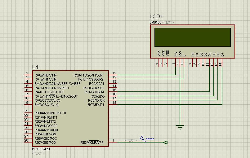
It should be very easy for most of you, but I need help urgently! I need to drive 16*2 LCD with PIC18F2423 MCU. I have a code in asm. However there are mistakes there:
1) the initialization time is too high (5-6 sec) have no idea why :-(
2) all the letters doubled, like 'HHEELLOO ...'...
I gues it somehow connected with PCL register, but I am too newbe to figure out myself ... please help!
Thank you in advance.
Vitaliy
It should be very easy for most of you, but I need help urgently! I need to drive 16*2 LCD with PIC18F2423 MCU. I have a code in asm. However there are mistakes there:
1) the initialization time is too high (5-6 sec) have no idea why :-(
2) all the letters doubled, like 'HHEELLOO ...'...
I gues it somehow connected with PCL register, but I am too newbe to figure out myself ... please help!
Code:
LIST P=18F2423		;directive to define processor
	#include <P18F2423.INC>	;processor specific variable definitions


; LABEL EQUATES	;;;;;;;;;;;;;;;;;;;;;;;;;;;;;;;;;;;;;;;;;;;;

Timer1	EQU	20		; 1ms count register
TimerX	EQU	21		; Xms count register
Var	EQU	22		; Output variable
Point	EQU	23		; Program table pointer
Select	EQU	24		; Copy of RS bit
OutCod	EQU	25		; Temp store for output code
Var1	EQU 26			; First digit

RS	EQU	1		; Register select output bit
E	EQU	2		; Display enable

; PROGRAM BEGINS ;;;;;;;;;;;;;;;;;;;;;;;;;;;;;;;;;;;;;;;;;;;

	ORG	0		; Place machine code
	NOP			; for ICD mode

	BANKSEL	TRISC		; Select bank 1
	CLRF	TRISC			; All outputs
	MOVWF	TRISC		; Initialise display port
	BANKSEL PORTC		; Select bank 0
	CLRF	PORTC		; Clear display outputs

	GOTO	Start		; Jump to main program


; SUBROUTINES ;;;;;;;;;;;;;;;;;;;;;;;;;;;;;;;;;;;;;;;;;;;;;;

; 1ms delay with 1us cycle time (1000 cycles)...............

Onems	MOVLW	D'249'		; Count for 1ms delay
	MOVWF	Timer1		; Load count
Loop1	NOP			; Pad for 4 cycle loop
	DECFSZ	Timer1		; Count
	GOTO	Loop1		; until Z
	RETURN			; and finish


; Delay Xms, X received in W ...............................

Xms	MOVWF	TimerX		; Count for X ms
LoopX	CALL	Onems		; Delay 1ms
	DECFSZ	TimerX		; Repeat X times
	GOTO	LoopX		; until Z
	RETURN			; and finish


; Generate data/command clock siganl E .....................

PulseE	BSF	PORTC,E		; Set E high
	CALL	Onems		; Delay 1ms
	BCF	PORTC,E		; Reset E low
	CALL	Onems		; Delay 1ms
	RETURN			; done


; Send a command byte in two nibbles from RB4 - RB7 ........

Send	MOVWF	OutCod		; Store output code
	ANDLW	0F0		; Clear low nybble
	MOVWF	PORTC		; Output high nybble
	BTFSC	Select,RS	; Test RS bit
	BSF	PORTC,RS	; and set for data
	CALL	PulseE		; and clock display register
	CALL	Onems		; wait 1ms for display

	SWAPF	OutCod		; Swap low and high nybbles
	MOVF	OutCod,W	; Retrieve output code
	ANDLW	0F0		; Clear low nybble
	MOVWF	PORTC		; Output low nybble
	BTFSC	Select,RS	; Test RS bit
	BSF	PORTC,RS	; and set for data
	CALL	PulseE		; and clock display register
	CALL	Onems		; wait 1ms for display
	RETURN			; done


;	Table of fixed characters to send ..................

Line1	ADDWF	PCL		; Modify program counter
	RETLW	'H'		; Pointer = 0
	RETLW	'E'		; Pointer = 1
	RETLW	'L'		; Pointer = 2
	RETLW	'L'		; Pointer = 3
	RETLW	'O'		; Pointer = 4
	RETLW	' '		; Pointer = 5
	RETLW	' '		; Pointer = 6
	RETLW	' '		; Pointer = 7
	RETLW	' '		; Pointer = 8
	RETLW	' '		; Pointer = 9
	RETLW	' '		; Pointer = 10
	RETLW	' '		; Pointer = 11
	RETLW	' '		; Pointer = 12
	RETLW	' '		; Pointer = 13
	RETLW	' '		; Pointer = 14
	RETLW	' '		; Pointer = 15

Line2	ADDWF	PCL		; Modify program counter
	RETLW	'W'		; Pointer = 0
	RETLW	'O'		; Pointer = 1
	RETLW	'R'		; Pointer = 2
	RETLW	'L'		; Pointer = 3
	RETLW	'D'		; Pointer = 4
	RETLW	' '		; Pointer = 5
	RETLW	' '		; Pointer = 6
	RETLW	' '		; Pointer = 7
	RETLW	' '		; Pointer = 8
	RETLW	' '		; Pointer = 9
	RETLW	' '		; Pointer = 10
	RETLW	' '		; Pointer = 11


; Initialise the display....................................

Init	MOVLW	D'10'		; Load count for 100ms delay
	CALL	Xms		; and wait for display start
	MOVLW	0F0		; Mask for select code
	MOVWF	Select		; High nybble not masked

	MOVLW	0x30		; Load initial nibble
	MOVWF	PORTC		; and output it to display
	CALL	PulseE		; Latch initial code
	MOVLW	D'5'		; Set delay 5ms
	CALL	Xms		; and wait
	CALL	PulseE		; Latch initial code again
	CALL	Onems		; Wait 1ms
	CALL	PulseE		; Latch initial code again
	BCF		PORTC,4		; Set 4-bit mode
	CALL	PulseE		; Latch it

	MOVLW	0x28		; Set 4-bit mode, 2 lines
	CALL	Send		; and send code
	MOVLW	0x08		; Switch off display
	CALL	Send		; and send code
	MOVLW	0x01		; Code to clear display
	CALL	Send		; and send code
	MOVLW	0x06		; Enable cursor auto inc
	CALL	Send		; and send code
	MOVLW	0x80		; Zero display address
	CALL	Send		; and send code
	MOVLW	0x0C		; Turn on display
	CALL	Send		; and send code

	RETURN			; Done


; Send the fixed message to the display.....................

OutMes	CLRF	Point		; Reset table pointer
	BSF	Select,RS	; Select data mode

Mess1	MOVF	Point,W		; and load it
	CALL	Line1		; Get ASCII code from table
	CALL	Send		; and do it
	MOVLW	D'250'		; Load count to wait 250ms
	CALL	Xms			; so numbers are visible
	INCF	Point		; point to next character
	MOVF	Point,W		; and load the pointer
	SUBLW	D'7'		; check for last table item
	BTFSS	STATUS,Z	; and finish if 16 done
	GOTO	Mess1		; Output character code

	MOVLW	0xC0		; Move cursor to line 2
	BCF	Select,RS	; Select command mode
	CALL	Send		; and send code
	CLRF	Point		; Reset table pointer
Mess2	MOVF	Point,W		; and load it
	CALL	Line2		; Get fixed character
	BSF	Select,RS	; Select data mode
	CALL	Send		; and send code
	MOVLW	D'250'		; Load count to wait 250ms
	CALL	Xms		; so numbers are visible
	INCF	Point		; next character
	MOVF	Point,W		; Reload pointer
	SUBLW	D'11'		; and check for last
	BTFSS	STATUS,Z	; Skip if last
	GOTO	Mess2		; or send next
	RETURN			; done


; MAIN PROGRAM ;;;;;;;;;;;;;;;;;;;;;;;;;;;;;;;;;;;;;;;;;;;;;

Start	CALL	Init		; Initialise the display
	CALL	OutMes		; Display fixed characters

END
Thank you in advance.
Vitaliy