Continue to Site

Welcome to EDAboard.com

Welcome to our site! EDAboard.com is an international Electronics Discussion Forum focused on EDA software, circuits, schematics, books, theory, papers, asic, pld, 8051, DSP, Network, RF, Analog Design, PCB, Service Manuals... and a whole lot more! To participate you need to register. Registration is free. Click here to register now.

[SOLVED] Driving capacitive load from MCU port

Status
Not open for further replies.

mrinalmani

Advanced Member level 1
Joined
Oct 7, 2011
Messages
463
Helped
60
Reputation
121
Reaction score
58
Trophy points
1,318
Location
Delhi, India
Activity points
5,285
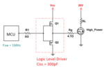
What is a rough limit of capacitive load that can be driven safely from an MCU port?
It may have something to do with the pulsed current capability of the port, which unfortunately is not stated in datasheets.
Is 500pF safe to drive directly from the port?
Thanks!

- - - Updated - - -

Also, is the port current clamped internally to the limit specified by the manufacturers or do we need to ensure this limit externally by using appropriate resistors. In other words, if we short a port that is high, will it fry of will it clamp the current to a few mA?
Thanks again!
 

Is 500pF safe to drive directly from the port?
Safe in so far that you don't risk to damage the output port. But the capacitive load is creating considerable ground bounce and supply current pulses and thus may be unwanted in sensitive circuits. At worst case, the switching interferences can e,g, cause a PLL to loose lock, or ruin the accuracy of on-chip analog measurements.

It's a good practice to isolate larger load capacitances like MOSFET gates or cables with a series resistor.
 
The internal resistance of CMOS drivers is determined by RdsOn plus internal fixed Rd values. e.g. VLC2 types use lower Rd inside.

Calculating the internal,resistance
Rs-=VOL/IOL and Rs+=(Vcc-VOH)/IOH , gives rise to older CMOS in the range of 200 Ohms and newer LVC2 type with 25 Ohms. This improves slew rate but also the short circuit current and dissipation loss , P=VC²xf increases with frequency of charge & discharge rate, f.

Device maximum power dissipation affected by Vcc , C, Rs when driving Capacitive loads. In Charge Pump designs, this is common to see large current.

The step response current spike may cause interference , or in your case may be used for some other purpose?

What is your application?
 
My application is very general...
A power MOSFET has to be driven. The driver circuit has a MOSFET based push-pull configuration. The driver receives input from the MCU.
(Please refer to the attachment)
Various drivers are available with Ciss ranging from approximately 10pF to 500pF. And as expected, the ones with higher current capability have higher input capacitance.

Now, I want to know how high can I climb on the capacitance ladder without falling down!
 

Attachments

  • Capture26.PNG
    Capture26.PNG
    22.6 KB · Views: 120

Driving MOSFET requires intuitive understanding that capacitance and charge dump current is high only during transistion. The effective series resistance of Gate is low so Rg is added to limit gate current which affects rise/fall time. Sometimes diodes are used to control each slope.

The current gain in each stage depends on RdsOn which requires a predriver stage to go from say 10mA to 10A. Depending on rise time desired and dead time to prevent shoot-thru in complementary drivers. Normally CMOS is well balanced but external MOSFETs require care when bridged. Single ended drivers are easier, but care in slew rate with ESL is required as you increase voltage, current and rise time , especially when using 1GW IGBT switches. No sweat for your levels. ;)
 
The driver circuit you are showing in post #4 won't give full output swing when built from enhancement mode MOSFETs. It's rather unlikely that a real driver uses this configuration (complementary source follower).

Reverting to my previous post, there's no clear limit for load capacitance. It depends on many circuit parameters, layout, bypassing, number of CPU ground pins, existence of critical circuit functions.
 
Logic level drivers are a key point as well as number of internal stages.

Here is one with CISS = 9pF and Iout=2.5ohm 6A 18V and 2.4~5V input.
But you need 24V
**broken link removed**
 

All right I get it.
From what I have learnt from your previous post (#3), it appears that if at all a series resistor be used, the values must be in tens of ohms (Since the internal resistance is as high as 25 ohm, small values of external will not help much). Adding such a large resistor will certainly flatten the slew.
As a confirmation I would want to ascertain whether it is a standard practice to drive small capacitive loads directly from the MCU without using a series gate resistor.
And also, what in your opinion could be rough value of capacitance that would demand an external resistor, assuming that the charge/discharge rate is low enough to contribute to any significant average current.
 

Depends on Use. If for high PWM, not a good match to have much more than few hundred pF load. if using Rs value could be equal to driver ESR to split source dissipation. Thus 25 Ohms or ARM and LCV 2 devices. Otherwise an intermediate driver with external power driver as I suggested.

Often simple power calculations are adequate P=VC²xf but Vg iCSS is not linear so you have Cdv/dt and V*dC/dt both drive input current.
 
Thanks!
One last thing... when selecting a microcontroller, how do we know if the channel resistance will be in the range of 25 ohm or 200 ohm?
Or is there no way to tell until we have experimentally figured it out?
 

Modelling the port output as a resistor is an improper simplification. Rdson is only valid at low voltage drops, at higher currents the MOSFET is operated in saturation and acting more like a current source.

Rdson can be estimated from the datasheet Vol and Voh specifications, you'll notice that the actual value undergoes a large type variation of at least 1:2, it's in addition temperature and voltage dependant.

Some datasheet also specify complete I/V characteristics or a short circuit current. According to what's previously said, you rarely want to utilize the maximum port current, in so far the information isn't often needed by developers.

In case of doubt, I would place a series resistors above 50 or 100 pF load capacitance even for infrequently switching outputs.
 

In case of doubt, I would place a series resistors above 50 or 100 pF load capacitance even for infrequently switching outputs.
Thanks!
Many datasheets provide rise/fall time of ports when loaded with 50pF (an indication that direct 50pF is safe?)
Anyway, I will stick to capacitance below 100pF when selecting drivers, driven directly from MCU ports.

Also...
Post #10 is not posted by me but probably by Mr. Skyguy. I dont know what it appears to others, but from my profile it shows post #10 posted by me!
Thanks everyone again!
 

Thanks!
One last thing... when selecting a microcontroller, how do we know if the channel resistance will be in the range of 25 ohm or 200 ohm?
Or is there no way to tell until we have experimentally figured it out?

Oops.. ( Fat fingers) Reposted correctly

As usual, the ESR or RdsOn or the output impedance is an incremental change in VI with Ohms Law on the datasheet VOL/IOL for low side driver and (VCC-VOH)/IOH for high side.

I have no idea why they dont spec this for ref purposes.

Experimentally matching the source impedance with an equal value will drop voltage in half. .. for a short term test. or load it with 100 Ohms and compute source impedance from R ratio drop.

- - - Updated - - -

Thanks!
Many datasheets provide rise/fall time of ports when loaded with 50pF (an indication that direct 50pF is safe?)
Anyway, I will stick to capacitance below 100pF when selecting drivers, driven directly

CMOS is usually short circuit protected by design depending on Vcc. 50pF std value represents output driving a fanout of 5 or 10 CMOS loads, I recall. Power Mosfets are naturally higher input capacitance, ICSS, but not a threat to driver.
 
Status
Not open for further replies.

Similar threads

Part and Inventory Search

Welcome to EDABoard.com

Sponsor

Back
Top