Continue to Site

Welcome to EDAboard.com

Welcome to our site! EDAboard.com is an international Electronics Discussion Forum focused on EDA software, circuits, schematics, books, theory, papers, asic, pld, 8051, DSP, Network, RF, Analog Design, PCB, Service Manuals... and a whole lot more! To participate you need to register. Registration is free. Click here to register now.

Driving a PNP transistor from an NPN transistor?

Status
Not open for further replies.

ferrariracers1

Newbie level 6
Joined
Jun 24, 2010
Messages
12
Helped
0
Reputation
0
Reaction score
0
Trophy points
1,281
Location
India
Activity points
1,380
Hello everybody!... I hope you all are fine......Recently i am stuck with a problem of connecting the output of an NPN transistor to the input of a PNP transistor....I cant do the connection....So it would be very helpful to me if any one of you can explain it to me as to how can i connect the circuit!!.....thank you!!!:grin:
 

Connecting the NPN collector to PNP base (usually through a current limiting resistor) forms a basic complementary amplifier.

Depending on the circuit's purpose, there would be additional elements like bias network, load, feedback, power supply ...
 

Perhaps the most common combination NPN with PNP is the video amplifier. In this situation the circuit provides gain starting almost from DC and is not reversing the polarity of the signal.

**broken link removed**
 

Thanx for the suggestions....I will definitely work on them....Actually the circuit is of an LED chase.....It will be driving LED chains of approx 5a current consumption each.....So from the outputs of decade count 4017b, transistors BC57 are attached and from them PNP transistors 2n6107 are attached....I also found zener diodes....but couldnt understand their function....So woul u please ellaborate their function to me??
 

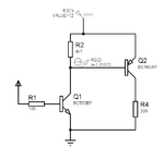
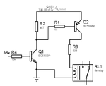
You probably mean something like this that lets you control a high side switch (PNP) using logic level input (0-5v).
The resistor values will be different according to your needs

0-5v_pnp_relay.gif

Alex
 
Yes alexan_e...this is exactly what i wanted....Thank you so much.......But could you tell me one thing???....Why are the zener diodes used over there?
 

I have no zener diode in the circuit and I don't know how it is used in the circuit you mean, you can post a schematic.

The operation of my circuit is quite simple, the PNP has the emitter connected to the power supply which is 12v, we know that when the base-emitter has a voltage difference above 0.7v (in the correct polarity) then the transistor conducts.
It wouldn't be possible to control that PNP with a 0 or 5v input because in both cases the PNP bias would be 12-5=7v and 12-0=12v.
That is why the NPN transistor is used, to translate the 0-5v to 12v-0.
When the base of the NPN has 0v then the transistor is off, in that case R2 works as a pull up ans provides 12v to the base of the PNP so it stays off.
When the base of the NPN gets 5v then it is turned on , the current flows through the transistor and R2 and creates a voltage drop on R2 which provides the base of the NPN with a voltage of about 0v and it turns on.

Alex
 
  • Like
Reactions: lukap1

    lukap1

    Points: 2
    Helpful Answer Positive Rating
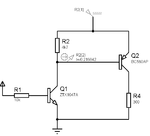
In Alex's circuit R2 should be across the PNP base and emiter. The connection shown wastes power.
 

R1 limits the base current of Q2, would you let Q1 provide the max current it can to the PNP?
Why would you want to depend on the current gain of Q1 or the value of R4?

Alex
 

If R2 is across the base the voltage on it is less than .8V. This means less than .2 mA less drive to Q2. Not enough to worry about.
 

Would that 1.3A base current make you worry or should I set it higher?

pnp_no_base_resistor.gif

Alex
 

Sorry. I did not think to say that you keep the original R1 in place from NPN to PNP.
 

But that is why I said that the maximum current would depend on the base resistor of the NPN and the current gain so my question is still the same, why would you want to depend on the NPN transistor gain and resistor.
If I replace Q1 with ZTX1047A with the same resistor values as the original circuit and the PNP base resistor removed then the PNP base gets 200mA

pnp_no_base_resistor_ZTX1047.gif

Alex
 

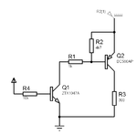
We are talking past one another. Put the 1K R1 from the collector of Q1 to the base of Q2 ( PNP). Keep R2 from base of Q2 to V+.
 

Ok, there was a mix-up because R1 in my original schematic was in a different position from the new one, you meant R1 of the original schematic and I thought of the new schematic.
Anyway what you mean is this and would work fine, the difference would be about 8mW for R2.

pnp_from_npn2.gif

Alex
 

OK. The advantage to doing it this way is that the base resistor can be fairly low in value without major loss of drive current and the lower the resistance the better the turn off performance.
 

The operation of my circuit is quite simple,

nothing is simple

It wouldn't be possible to control that PNP with a 0 or 5v input because in both cases the PNP bias would be 12-5=7v and 12-0=12v.
That is why the NPN transistor is used, to translate the 0-5v to 12v-0.

in otherwords, VBE of the pnp would be too high in both cases (7V & 12V), and could never be turned ON?
a pnp is ON for VBE < .7V, and OFF for VBE > .7 V ?? is this correct?

(i know how an npn works, dont explain that to me)
 

it is my mistake for misinterpreting your intension.

in otherwords, VBE of the pnp would be too high in both cases (7V & 12V), and could never be turned ON?
No the opposite, the transistor will always be ON
When the base has a voltage that is 0.7v lower from the emitter or more then the transistor conducts

Ve=12v, Vb=0v , the base is 12v lower than the emitter, the transistor is on
Ve=12v, Vb=5v , the base is 7v lower than the emitter, the transistro is on
 

thank u, very clever circuit
 

Status
Not open for further replies.

Similar threads

Part and Inventory Search

Welcome to EDABoard.com

Sponsor

Back
Top