Hayaichi
Newbie level 1
driving a mosfet
Hi, I've been trying for a couple weeks now to drive a N-channel mosfet of mine from an ATmega48 microcontroller using PWM. Mosfet datasheet: http://www.fairchildsemi.com/ds/HU/HUFA76409P3.pdf Microcontroller datasheet: http://www.atmel.com/dyn/resources/prod_documents/doc2545.pdf Circuit diagram(not the best, should be understandable though):
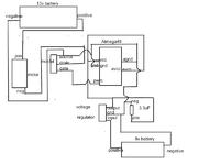
There's also a diode internally parallel to the mosfet's channel that's not shown in the diagram. I'm using two battery sources, one 12.88V, to power a motor through the mosfet, the other 7.79V, regulated down to 4.96V and supplying the power to the microcontroller. The mosfet is on it's own breadboard, jumpered to the microcontroller, which is on a different breadboard. The motor is jumpered to about an inch from the mosfet. None of the wires exceed 2 inches, except the power lines, which are alligator clips, and right at about 1.5 feet. The code I have in the microcontroller seems to be working fine, the pin I'm using for PWM outputs a 0-5V rectangular waveform corresponding to whatever I set to the duty cycle(50%, 75%, etc) to, and oscillating at whatever I set the PWM frequency(32khz, 16khz, etc) to. I've tried 4 different frequencies. At 32khz, the voltage drop across the motor was something like 2.34V at 75% duty cycle. I switched to 16khz, and at the same duty cycle, the voltage across the motor was either the same or slightly higher. At 4khz, The voltage across the motor was at about 5.5V for a 50% duty cycle. At 0.5khz, the voltage drop across the motor was 11.21V at 50% duty cycle, and 12.2V at 75% duty cycle. I've tried a 1k resistor from gate-source, that made no noticable difference. The microcontroller is supposed to be able to source and sink about 20ma continuously, and the total gate charge is about 15nC, so from what I can see it should be able to operate at worst 1mhz. If I can ever get this duty cycle problem cleared up I'd like to make a H-bridge to drive a motor. So I was thinking motor drivers might solve my problem, but I can't quite understand how if the microcontroller should be able to charge and discharge the gate fast enough. Anyone have any ideas what changes I could make to get the actual duty cycle of the mosfet to reflect the duty cycle the microcontroller is outputting?
Hi, I've been trying for a couple weeks now to drive a N-channel mosfet of mine from an ATmega48 microcontroller using PWM. Mosfet datasheet: http://www.fairchildsemi.com/ds/HU/HUFA76409P3.pdf Microcontroller datasheet: http://www.atmel.com/dyn/resources/prod_documents/doc2545.pdf Circuit diagram(not the best, should be understandable though):
There's also a diode internally parallel to the mosfet's channel that's not shown in the diagram. I'm using two battery sources, one 12.88V, to power a motor through the mosfet, the other 7.79V, regulated down to 4.96V and supplying the power to the microcontroller. The mosfet is on it's own breadboard, jumpered to the microcontroller, which is on a different breadboard. The motor is jumpered to about an inch from the mosfet. None of the wires exceed 2 inches, except the power lines, which are alligator clips, and right at about 1.5 feet. The code I have in the microcontroller seems to be working fine, the pin I'm using for PWM outputs a 0-5V rectangular waveform corresponding to whatever I set to the duty cycle(50%, 75%, etc) to, and oscillating at whatever I set the PWM frequency(32khz, 16khz, etc) to. I've tried 4 different frequencies. At 32khz, the voltage drop across the motor was something like 2.34V at 75% duty cycle. I switched to 16khz, and at the same duty cycle, the voltage across the motor was either the same or slightly higher. At 4khz, The voltage across the motor was at about 5.5V for a 50% duty cycle. At 0.5khz, the voltage drop across the motor was 11.21V at 50% duty cycle, and 12.2V at 75% duty cycle. I've tried a 1k resistor from gate-source, that made no noticable difference. The microcontroller is supposed to be able to source and sink about 20ma continuously, and the total gate charge is about 15nC, so from what I can see it should be able to operate at worst 1mhz. If I can ever get this duty cycle problem cleared up I'd like to make a H-bridge to drive a motor. So I was thinking motor drivers might solve my problem, but I can't quite understand how if the microcontroller should be able to charge and discharge the gate fast enough. Anyone have any ideas what changes I could make to get the actual duty cycle of the mosfet to reflect the duty cycle the microcontroller is outputting?