Continue to Site

Welcome to EDAboard.com

Welcome to our site! EDAboard.com is an international Electronics Discussion Forum focused on EDA software, circuits, schematics, books, theory, papers, asic, pld, 8051, DSP, Network, RF, Analog Design, PCB, Service Manuals... and a whole lot more! To participate you need to register. Registration is free. Click here to register now.

Driving 24Vdc Solenoid valve with Transistor or MOSFET?

Status
Not open for further replies.

Eng.Hassan

Newbie level 4
Newbie level 4
Joined
Sep 7, 2014
Messages
7
Helped
0
Reputation
0
Reaction score
0
Trophy points
1
Visit site
Activity points
57
Hello every one,

I have bought a solenoid valve that requires 24Vdc with 750mA and I was trying to use the 2N222A transistor to drive it though a Xbee which give 3.3Vdc but just seconds after the connection it get very hot ( I mean the BJT ) I looked at the Datasheet and it states that the max collector current is 1Amp ?!! I don't know how to resolve this issue and I'm not quite sure if the MOSFET will solve this heat sink problem?

Any suggestion or recommendation?

Thanks & Regards,

P.S.
1) I'm using a 24Vdc 2.8Amp power supply to supply the solenoid valve
2) I'm using the normal connection shown in the diagram but with 24Vdc
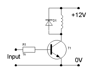
6151997700_1413508657.gif
 

The 2N2222A isn't really up to switching task you're asking it to do... there's 3 key areas it's failing in:

1. The (maximum) collector current rating for the 2N2222A seems to vary all over the place depending upon manufacturer/package etc (a quick Google around revealed values from 600 mA - 1A). Depending on your variant, you might be exceeding the 'absolute maximum' spec for your part, which is a very bad thing to do ;)

More importantly, though:

2. The "DC current gain" family of curves in the datasheet are a useful guide* as to the drive requirements for a BJT. From the data sheet I found at https://users.ece.utexas.edu/~valvano/Datasheets/2N2222.pdf, Figure 3 (with some generous extrapolation) suggests that the current gain of the transistor could be expected to be as poor as ~20 at your desired 750 mA load current. That means you'd need to provide it with 750/20 ~= 37 mA of base current for it to enter saturation. With the circuit you have shown, the maximum possible base current is: 3.3V (from the Xbee) - 0.7V (Vbe drop) / 1K = 2.6 mA, over an order of magnitude too small! As such, the transistor can't turn on fully, and is dissipating large amounts of heat.

3. How much heat? The transistor dissipation = collector current x Vce voltage. Figure 4 shows the sort of Vce you'd expect for a given base current/collector current combination. At 2.6 mA base current, Vce is off the chart (> 1 V) for collector current somewhere between 150 & 500 mA. This tells us that the transistor a) won't be able to sink the required 750 mA, and b) if it did, it has many VOLTS of drop between collector and emitter. Thus the package dissipation is likely to be in the order of WATTS, and far in excess of the specified absolute maximum ratings. I have no doubt it gets hot!

So - what to do?

Easy. Get a bigger (+better) transistor. If you like BJT's, then just beware that bigger devices often have poorer current gains - an elegant solution in your application is the so called "darlington" configuration (Google it). You can get them as single devices (eg. BD681) too and such a part would happily run from your 1K base resistor.

Alternatively, you can use a power MOSFET - no 1K resistor needed (although a pull-down of similar value isn't a bad safety feature to add) and just about anything in a TO-220 package will have enough grunt for you. Just beware their threshold voltage spec - at 3.3V you might be a little marginal for some devices. (Check the drain current vs Vgs specifications/plots).

Good luck!


* Note: I said GUIDE. The DC current gain of a transistor is an extremely poorly controlled device parameter - and strongly temperature sensitive - and should NEVER be used to design bias networks. Use them for sanity checking base current drive requirements ONLY!
 
Last edited:

Hi,

Here is two possibilities of problem,

1, Insufficient Base current (will put the transistor in linear region and make it consume more power)
2, according to your actual plan it will dissipate 0.75A * 1V = 0.75W that also can be possible for small heat, you can make it dissipate through a small heat sink or through PCB.

Insufficient Base current:
For a transistor to work in switch, it should have 1 / 10th current of collector, in your case 75mA. which is not actually provided from the source of two reasons
1, due to Base resistor (Rb should be (3.3 - 0.7) / 0.075)
2, inability of source

If your source is rated less than 75mA, It cant provide it so you may need a another transistor in the output.
 

The 2N2222A isn't really up to switching task you're asking it to do... there's 3 key areas it's failing in:

1. The (maximum) collector current rating for the 2N2222A seems to vary all over the place depending upon manufacturer/package etc (a quick Google around revealed values from 600 mA - 1A). Depending on your variant, you might be exceeding the 'absolute maximum' spec for your part, which is a very bad thing to do ;)

More importantly, though:

2. The "DC current gain" family of curves in the datasheet are a useful guide* as to the drive requirements for a BJT. From the data sheet I found at https://users.ece.utexas.edu/~valvano/Datasheets/2N2222.pdf, Figure 3 (with some generous extrapolation) suggests that the current gain of the transistor could be expected to be as poor as ~20 at your desired 750 mA load current. That means you'd need to provide it with 750/20 ~= 37 mA of base current for it to enter saturation. With the circuit you have shown, the maximum possible base current is: 3.3V (from the Xbee) - 0.7V (Vbe drop) / 1K = 2.6 mA, over an order of magnitude too small! As such, the transistor can't turn on fully, and is dissipating large amounts of heat.

3. How much heat? The transistor dissipation = collector current x Vce voltage. Figure 4 shows the sort of Vce you'd expect for a given base current/collector current combination. At 2.6 mA base current, Vce is off the chart (> 1 V) for collector current somewhere between 150 & 500 mA. This tells us that the transistor a) won't be able to sink the required 750 mA, and b) if it did, it has many VOLTS of drop between collector and emitter. Thus the package dissipation is likely to be in the order of WATTS, and far in excess of the specified absolute maximum ratings. I have no doubt it gets hot!

So - what to do?

Easy. Get a bigger (+better) transistor. If you like BJT's, then just beware that bigger devices often have poorer current gains - an elegant solution in your application is the so called "darlington" configuration (Google it). You can get them as single devices (eg. BD681) too and such a part would happily run from your 1K base resistor.

Alternatively, you can use a power MOSFET - no 1K resistor needed (although a pull-down of similar value isn't a bad safety feature to add) and just about anything in a TO-220 package will have enough grunt for you. Just beware their threshold voltage spec - at 3.3V you might be a little marginal for some devices. (Check the drain current vs Vgs specifications/plots).

Good luck!


* Note: I said GUIDE. The DC current gain of a transistor is an extremely poorly controlled device parameter - and strongly temperature sensitive - and should NEVER be used to design bias networks. Use them for sanity checking base current drive requirements ONLY!

Dear thylacine1975,

I'm completely speechless and so grateful on how you thoroughly replied to my inquiry with such in depth and detailed! This is how the spirit should be in any technical forum even with repeated inquiries, it is always good to answer and refer the requester to the right referral.

Sir, I really thank you and wish you a great weekend and will let know how your recommendation will go, currently I'm evaluating using either BD681 as I'm concerned with the base current that should be limited not more than 2mA as Xbee devices data sheet states. I bought MOSFET TO-220 package and hopes will work as anticipated.

- - - Updated - - -

Use TIPx transistors.

Thank you very much milan, I will look at them , I will let you know after doing the simulation with the result if they could be a good solution to my case.

Thanks again ..
 

There is a different class of transistor switch with ultralow Vce and Rce with higher hFE and gain at saturation. I wont get into the epitaxial differences but instead of 10:1 Ic:Ib specs for switch operation they are 50:1 and usually specialized by Diodes Inc and some others. They also class the devices for NPN with Rce like MOSFETs with RdsOn except have much lower capacitance during switching, which is not critical for a solenoid as it is switched slow.

Butthe Nch Enh=mode MOSFET with protection may be best solution here. Make sure you add high current reverse diode across Coil.

Choose RdsOn for <0.1W dissipation for simple layout or 0.1W=0.75A^2*R so RdsOn < 177 mΩ is fine.

What that 750mA steady state or surge?

hundreds to choose from Digikey or Mouser from menu.
Code:
PN    Manufacturer    Unit Price (CAD)    Packaging
AOD444    Alpha & Omega Semiconductor Inc    0.81    Cut Tape (CT)
AO4438    Alpha & Omega Semiconductor Inc    1.02    Cut Tape (CT)
AOD2610    Alpha & Omega Semiconductor Inc    1.15    Cut Tape (CT)
TPH14006NH,L1Q    Toshiba Semiconductor and Storage    1.3    Cut Tape (CT)
2SK4017(Q)    Toshiba Semiconductor and Storage    0.8    Bulk
FDN5630    Fairchild Semiconductor    0.66    Cut Tape (CT)
IRLML0060TRPBF    International Rectifier    0.69    Cut Tape (CT)
AO6420    Alpha & Omega Semiconductor Inc    0.54    Cut Tape (CT)
DMN6068LK3-13    Diodes Incorporated    0.71    Cut Tape (CT)

Even if 2N2222 could handle more than 500mA the Rce=2V/0.5A = 4 Ohms max
 

Status
Not open for further replies.

Similar threads

Part and Inventory Search

Welcome to EDABoard.com

Sponsor

Back
Top