karthik.pillai
Newbie level 1
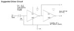
I would like to use inverter IC SN74HCT04NSR for generating output level of 0 and -5V.
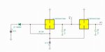
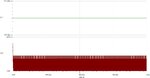
AS per the above suggested driver circuit, i have simulated the same in Tina using a single channel hex inverter SN74AHC1G04 as shown below and the simulated response as in the graph below. Can anyone suggest whether the implemented logic is correct for generating 0V and -5V output.
AS per the above suggested driver circuit, i have simulated the same in Tina using a single channel hex inverter SN74AHC1G04 as shown below and the simulated response as in the graph below. Can anyone suggest whether the implemented logic is correct for generating 0V and -5V output.