Continue to Site

Welcome to EDAboard.com

Welcome to our site! EDAboard.com is an international Electronics Discussion Forum focused on EDA software, circuits, schematics, books, theory, papers, asic, pld, 8051, DSP, Network, RF, Analog Design, PCB, Service Manuals... and a whole lot more! To participate you need to register. Registration is free. Click here to register now.

Dot matrix 16 * 56 soruce and sinking current issues

Status
Not open for further replies.

bakikoo

Newbie level 5
Joined
Sep 21, 2010
Messages
8
Helped
0
Reputation
0
Reaction score
0
Trophy points
1,281
Activity points
1,350
Hi all,
Im trying to build 16*56 dot matrix using 14 8*8 single color module.I'm using seven shift register for the columns and two shift register to scan the rows and two ULN2803 after the row shift registers to sink the current.

I've only tried one dot matrix 8*8 the brightness is good i think it's working fine on the 35 mA source current of the 74hc595.but i dont know if the DARLINGTON transistor is capable of sinking 56 led row since i only tested on 8 dot row.

I was thinking to put more ULN2803 in parallel to withstand the extra current that's the first approach

or change the design with high current source driver at rows and seven ULN2803 at columns to sink the current. but still dont know any good available current source . i checked some designs with BC557 npn transistor as current source but i think it can't source around 2A (35mA*56) for each row.

Any help will be great appreciated

Regards,
Amr
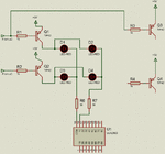
 

Thanks for your favorable reply.but how can i add more TIP42 to drive double current since i got 56 LEDs per rows and how much current each TIP42 can source ?
 

untitled.GIF
You can change R-base 470 - 1K, and R at ULN2803's output 39 - 100 ohm.
TIP42, IC = 6 A, HFE = 30.
 

I got the TIP42 it's very cost effective but now i only want to drive each led around 20mA do i still need the ULN2803 at each column to drive such current since 74HC595 can sink that much? Also i need around 1 A for each row so One TIP42 would be enough for that?
 

Each hc595's output pin can drive 35 mA, so, we don't need to add ULN2803. And to drive 1A, we can use one TIP42 for each row.

Each pin can give up to 35mA but the TOTAL current for all pins of the chip can't be more than 70mA

Continuous current through VCC or GND ±70 mA
 
Hi bakikoo;
To construct a 16x56 LED matrix circuit with 30-40 mA pulsed LED current I suggest the following

- at row side (LED anodes, 16 rows)
use a 74(HC, HCT)154 4-to-16 line decoder/demultiplexer instead of two shift register.
Right, it requires five output pins: the 4 addresses and one for inhibit all outputs (it is a must !!)
but the SW will be much more simpler and faster,
then use 16 pcs PNP (or PNP darlington) power transistors, like a TIP 124 or TIP142,
with a small (max 220 Ohm) basic resistors, for driving all the 16 rows.

- at column side (LED cathodes, 7 bytes = 56 columns)
use 56 pcs well valued current limiting resistors (10-150 Ohm, depends on the drivers and the LEDs)
Then
use the HC595 with ULN2803, or with 8pcs small PNP transistors using them as an emitter-follower.
or
use the tpic6b595, it does not require any additional driver (see the picture).
 

Attachments

  • tpic6b595_currents.jpg
    tpic6b595_currents.jpg
    73 KB · Views: 82
Last edited:
Of course 7 bytes = 56 columns ( modified :)
 

Thanks alot guys for your replay.
i think it's quite enough to sink with 74HC595 since i wont light the 8 leds at the same time but as Alexan pointed out that max current for IC 70mA so i'll put the driver IC as safe factors to be on the safe side.

@zuisti
Well using decoder will be much easier in SW but more pins will be required. i did the design with 2 shift register for the ROW but still dont know any downfalls for it other than SW.for the columns i'll use HC74595 + ULN2803 to sink the current

for the row driver whatever i use NPN or PNP transistor how can i pick the right base resistor to the source max current ?

and to drive each led at 20ms what series resistor should i put at each column?
As far as i know it should be 15 ohm to get 320mA if the current is continues so we will get 20mA since it 'll be only ON for time 1/16 of the total frame.

Regards,
Amr
 

Each pin can give up to 35mA but the TOTAL current for all pins of the chip can't be more than 70mA

Continuous current through VCC or GND ±70 mA

My mistake. I should think attentively before answering

@bakikoo
If i remember (sorry, it was long time ago i practiced it), giving to small resistor at output of ULN2803 can make LED on although output of HC595 is low.
 

Yes , you did hit the next problem i couldn't see after using high current driver.
if i did turn all leds ON then turn them off they are still barely ON ,i did replace the resistor with much higher value and still no luck!
 

I'm using Dot matrix 8*8. the common (pin10) of the ULN2803 is connected to voltage logic supply 5v
I'll try to connect the Vcc n GNd of this IC with a different supply and see how would it go.
 

Sorry for my quick observation it's not the whole leds.
Please check the attached picture i'm displaying Number 2 pattern i just noticed that there's the pattern plus it's shadow shifted up one row and barely lights up.
I assume it's kind of software glitch since it's not the whole leds

here's the code sample to display number 2 pattern

Code:
#include <mega32.h>
// SPI functions
#include <spi.h> 
#include <delay.h>


void spi_begin(void) {
  // set /SS = low to select SPI slave device.
  PORTB &= 0b11101111;
}

void spi_end(void) {
 
  // set new data by /SS = high then Low,
 
  
  PORTB |= 0b00010000;   
  PORTB |= 0b00000000;
 
}

void spi_send(char cData) {
  SPDR = cData;
 while(!(SPSR.7)) {
    ;  // wait for SPIF flag to be set
  }
  
}
// Declare your global variables here 
flash unsigned char symbols[10][8]=
	{       
	        
		{0x3C,0x66,0x66,0x66,0x66,0x66,0x66,0x3C},
		{0x1E,0x18,0x18,0x18,0x18,0x18,0x18,0x7E},
		{0x3C,0x66,0x66,0x30,0x18,0xC,0x7E,0x76},
		{0x7E,0x66,0x30,0x18,0x30,0x66,0x66,0x3C},
		{0x30,0x38,0x34,0x34,0x36,0x7E,0x30,0x78},
		{0x7E,0x66,0x6,0x3E,0x60,0x66,0x66,0x3C},
		{0x3C,0x66,0x6,0x3E,0x66,0x66,0x66,0x3C},
		{0x7E,0x66,0x66,0x30,0x30,0x18,0x18,0x18},
		{0x3C,0x66,0x66,0x3C,0x66,0x66,0x66,0x3C},
		{0x3C,0x66,0x66,0x66,0x7C,0x60,0x66,0x3C}
		
		
	};


char ticker=0x01;
char row=0;

// Timer 0 overflow interrupt service routine
interrupt [TIM0_OVF] void timer0_ovf_isr(void)
{


  // SPI transfer 
  spi_begin();
  //sending column data
  spi_send(symbols[2][row]); 
  //sending Row data; only one row is active at a time
  spi_send(~ticker); 
  spi_end();
  //selecting the next row  
  ticker=ticker<<1;
  
  row++;
  if(row==8){row=0;ticker=0x01;}
                                                         ;
} 

void main(void)
{
// Declare your local variables here

// Input/Output Ports initialization
// Port A initialization
// Func7=In Func6=In Func5=In Func4=In Func3=In Func2=In Func1=In Func0=In 
// State7=T State6=T State5=T State4=T State3=T State2=T State1=T State0=T 
PORTA=0x00;
DDRA=0xff;

// Port B initialization
// Func7=Out Func6=In Func5=Out Func4=Out Func3=In Func2=In Func1=In Func0=In 
// State7=0 State6=T State5=0 State4=0 State3=T State2=T State1=T State0=T 
PORTB=0x00;
DDRB=0xB2;

// Port C initialization
// Func7=In Func6=In Func5=In Func4=In Func3=In Func2=In Func1=In Func0=In 
// State7=T State6=T State5=T State4=T State3=T State2=T State1=T State0=T 
PORTC=0x00;
DDRC=0x00;

// Port D initialization
// Func7=In Func6=In Func5=In Func4=In Func3=In Func2=In Func1=In Func0=In 
// State7=T State6=T State5=T State4=T State3=T State2=T State1=T State0=T 
PORTD=0x00;
DDRD=0x00;

// Timer/Counter 0 initialization
// Clock source: System Clock
// Clock value: 921.600 kHz
// Mode: Normal top=FFh
// OC0 output: Disconnected
TCCR0=0x02;
TCNT0=0x00;

// Timer/Counter 1 initialization
// Clock source: System Clock
// Clock value: 0.977 kHz
// Mode: Normal top=FFFFh
// OC1A output: Discon.
// OC1B output: Discon.
// Noise Canceler: Off
// Input Capture on Falling Edge
// Timer 1 Overflow Interrupt: Off
// Input Capture Interrupt: Off
// Compare A Match Interrupt: On
// Compare B Match Interrupt: Off
TCCR1A=0x00;
TCCR1B=0x05;
TCNT1H=0x00;
TCNT1L=0x00;
ICR1H=0x00;
ICR1L=0x00;
OCR1AH=0x1c;
OCR1AL=0x20;
OCR1BH=0x00;
OCR1BL=0x00;

// Timer/Counter 2 initialization
// Clock source: System Clock
// Clock value: Timer 2 Stopped
// Mode: Normal top=FFh
// OC2 output: Disconnected
ASSR=0x00;
TCCR2=0x00;
TCNT2=0x00;
OCR2=0x00;

// External Interrupt(s) initialization
// INT0: Off
// INT1: Off
// INT2: Off
MCUCR=0x00;
MCUCSR=0x00;

// Timer(s)/Counter(s) Interrupt(s) initialization
TIMSK=0x11;

// Analog Comparator initialization
// Analog Comparator: Off
// Analog Comparator Input Capture by Timer/Counter 1: Off
ACSR=0x80;
SFIOR=0x00;

// SPI initialization
// SPI Type: Master
// SPI Clock Rate: 1843.200 kHz
// SPI Clock Phase: Cycle Half
// SPI Clock Polarity: Low
// SPI Data Order: MSB First
SPCR=0x50;
SPSR=0x00;

// Global enable interrupts
#asm("sei")

while (1)
      {
      // Place your code here
      // setting port B; output = MOSI, SCK, /SS, PB1(/OE)
  PORTB = 0;
  
  
      };
}
 

Attachments

  • DSC00024.JPG
    DSC00024.JPG
    886.8 KB · Views: 68

After sending single row, then clear all HC595 output and disable all row before process next row.

I agree ...
Read more:

---I assume it's kind of software glitch since it's not the whole leds
here's the code sample to display number 2 pattern ...

Hi bakikoo;
It is very difficult to read your above program without knowing the actual circuit. But I tried (I'm sorry, if not succeeded):

Assuming the followings:
-- you have (now) two Hc595 in a chain, the first for the columns, the second for the rows, and the second gets datas via spi (because you send the column datas first, followed by the row datas).
-- the hc595 shcp and the stcp pins are common, and the common stcp pin is connected to PORTB.4 (/SS ?, store-clock, need a positive pulse)
your code above is working (I think) but:

Your 'spi_end' function is wrong:
Code:
void spi_end(void) 
  // set new data by /SS = high [COLOR="#FF0000"]then Low[/COLOR],
   PORTB |= 0b00010000;   // high   
   [COLOR="#FF0000"]//PORTB |= 0b00000000; // this line does nothing !!! [/COLOR]
   PORTB &= 0b11101111;   // [COLOR="#FF0000"]low[/COLOR]
}

In this case the end of the main:
Code:
// setting port B; output = MOSI, SCK, /SS, PB1(/OE)
  PORTB = 0;
// Global enable interrupts
#asm("sei")
while (1)
      {
      // Place your code here
      };
} // end of main
and the whole 'spi_begin' function is unnecessary.

But ...
there are a shadow danger in your solution above: after the spi sending you switch to the new row immediately, so no enough time for switching off the prev row's driver.
The good method: first switch off all rows and only then switch into the new content. But using your circuit this is almost impossible, at least consumes much more time.
My recommendations:
- use separated shcp and stcp pins (yes, this also requires more (+2) output pins) for the columns and the rows (chain, later).
- or (as I wrote already) use a decoder IC at the row-side.

Other:
Not a luckily thing to place the whole displaying into the interrupt routine. Using only one character (like now) it may be good, but if a longer text is displayed, do not remain enough time to do also anything other (sending more bytes via SPI (with their waitings) will be not fast enough).
This method may be good for column scanning but in this case not (at least in my opinion). Instead, place the whole display routine into the main loop. You can use the timer (a flag) for the proper timing to get equal row-brightnesses.
 
This did fix the problem.
thanks guys for your great support
I did turned off the row before sending the next one and it consumes much more time as zuisti
pointed out but it did work.

I'll modifiy the code to run in main it'll be less bounded and can offer me more time to send the extra bytes. But what i dont understand How can i get equal row-brightnesses by using timer!?
 

Take a look at this example. Sorry i don't use your code, because i'm difficult to understand


Code C - [expand]
1
2
3
4
5
6
7
8
9
10
11
12
13
14
15
16
17
18
19
20
21
22
23
24
25
26
27
28
29
30
31
32
33
34
35
36
37
38
39
40
41
42
43
44
45
46
#define time_to_on  0x08
#define time_to_off 0x02
 
//init timer
TCCR1A=0x00;
TCCR1B=0x0A;
TCNT1H=0x00;
TCNT1L=0x00;
ICR1H=0x00;
ICR1L=0x00;
OCR1AH=0x10;
OCR1AL=0x00;
OCR1BH=0x00;
OCR1BL=0x00;
..
..
//scanning section
for (c=0;c<8;c++)
{
     for (a=0;a<56;a++)
     {
          b=buffer_data[a];
          d=b>>c; 
          if (d & 1) (sdata_1_a=0); else (sdata_1_a=1);
          hc595_clock_a=1;
          hc595_clock_a=0;
     };
    e=0;
    while (e==0) e=TIFR;
    TIFR|=16;
    OCR1AH=time_to_on;
    row=c;
    e3_138=1;  //138 is enabled
    hc595_strobe_a=1;
    hc595_strobe_a=0;
 
    e=0;
    while (e==0) e=TIFR;
    TIFR|=16; 
    OCR1AH=time_to_off;
 
    hc595_reset=0;//you can use these two lines or not.
    hc595_reset=1;
 
    e3_138=0;  //138 is disabled
};

 
Last edited:

Status
Not open for further replies.

Similar threads

Part and Inventory Search

Welcome to EDABoard.com

Sponsor

Back
Top