Continue to Site

Welcome to EDAboard.com

Welcome to our site! EDAboard.com is an international Electronics Discussion Forum focused on EDA software, circuits, schematics, books, theory, papers, asic, pld, 8051, DSP, Network, RF, Analog Design, PCB, Service Manuals... and a whole lot more! To participate you need to register. Registration is free. Click here to register now.

Does this super capacitor balancing work?

Status
Not open for further replies.
Joined
Jul 25, 2012
Messages
1,192
Helped
171
Reputation
342
Reaction score
162
Trophy points
1,343
Activity points
0
Does this super capacitor balancing circuit works?????? The capacitors are rated 2.7 V 3000F The capacitors should not charge more than 2.7 volts.
 

Attachments

  • sc.jpg
    sc.jpg
    190.7 KB · Views: 71

The circuit allows for +/- 0.6 V variation of individual capcitor voltage. With low voltage margin, you should better refer to an OP based balancing circuit, as it has been discussed in previous edaboard threads. The current strength of a balancing circuit should be selected according to the charge current and expectable capacitor inbalance.
 
@FvM

Can you please provide the links for op amp based balancing circuits. I didn't find one.

I changed the circuit a little. Will this work?
 

Attachments

  • super cap 4.rar
    12 KB · Views: 45
Last edited:

Can you please provide the links for op amp based balancing circuits. I didn't find one.
Not a specific problem with your question, but I wonder why a large share of Edaboard posts is querying information, that can be found either by a board or google search? I need to operate the same search machines!

https://www.edaboard.com/threads/204875/

I changed the circuit a little. Will this work?
How should it? By the way, Edaboard users can expect a schematic readable by eye. Simulation circuits are optional and particularly interesting for problems that need further analysis.
 
@FvM

I checked the link. It was not helpful. Can you provide more links.
 

I don't think the first circuit will work properly. There's nothing to balance the voltage between C2 and C3 or between C4 and C5.

I changed the circuit a little. Will this work?
Don't know, can't see it.
 

I don't think the first circuit will work properly. There's nothing to balance the voltage between C2 and C3 or between C4 and C5.
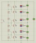
Yes, it should it be at least supplemented with a complementary driver for every tap. The other problem is the "loose" of +/- 0.6 V caused by transistor Vbe. So with 12 V input, the individual capacitor voltages can vary between 1.8 and 3.0 V. You could add a single bias diode for each transistor pair, reducing the loose to +/- 0.3 V.

Or use an OP based balancing circuit, as in the Epcos application note and other circuits discussed in the link.
 

The capacitors are rated 2.7 V 3000F
You might have to rethink the idea of using opamps for this. Even with a current of 1 amp, it would take nearly an hour to charge/discharge one capacitor by 1 volt.

Maybe power transistors/Darlingtons/MOSFETs controlled by opamps?
 
  • Like
Reactions: FvM

    FvM

    Points: 2
    Helpful Answer Positive Rating
@ FvM

Can I use this circuit by extending the opamp stages to 6?

**broken link removed**

I will be using 12 V solar panel. The voltage will not exceed 14 V. I will replace the 310F supercapacitors in the circuit with 3000F SC.
 

Can I use this circuit by extending the opamp stages to 6?
Yes, it looks very similar to the active balancing concept suggested in the Epcos application note. It can be extended to any number of cells.

I must confess, that I didn't think about the restriction of simple OP circuit to a two-cell stack. Although it can be extended to multiple cells, it doesn't make much sense in this case.
 

@ FvM

I want to know can I use this circuit **broken link removed** by extending it to 6 supercapacitors. There will be 6 Op amp stages.

Can I use 2.& v Zener instead of LM 385??????
 
Last edited:

The reference voltage must be clearly below the circuit threshold. Accuracy with 2V4 Z-diode won't be very good, the voltage divider has to be recalculated of course.


Status
Not open for further replies.

Similar threads

Part and Inventory Search

Welcome to EDABoard.com

Sponsor

Back
Top