Continue to Site

Welcome to EDAboard.com

Welcome to our site! EDAboard.com is an international Electronics Discussion Forum focused on EDA software, circuits, schematics, books, theory, papers, asic, pld, 8051, DSP, Network, RF, Analog Design, PCB, Service Manuals... and a whole lot more! To participate you need to register. Registration is free. Click here to register now.

Do you think the output of this encoder is logic?

Status
Not open for further replies.

powersys

Advanced Member level 1
Joined
Nov 29, 2005
Messages
439
Helped
3
Reputation
6
Reaction score
2
Trophy points
1,298
Activity points
4,981
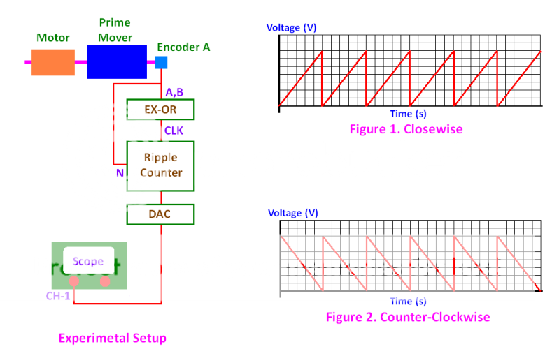
My experimental setup is as shown in attached image.
The prime mover is used to drive the motor at a constant speed, e.g. 1000rpm.
The encoder used in the system is Hengstler RI58-O/2000AS.41RB with 2000ppr.
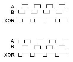
Output signals A and B of the encoder are input to an EX-OR gate.
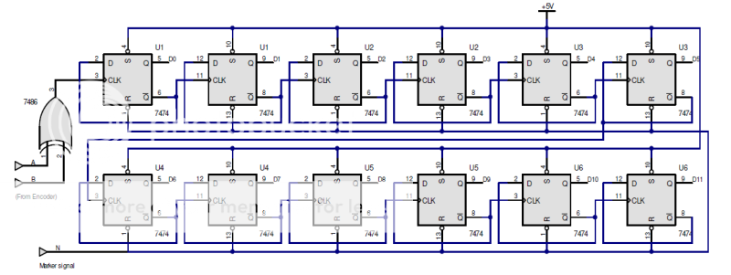
The CLK signal is then input to a 12-bit counter (uni-directional).
Index signal N from the encoder is used to reset the counter to zero every revolution made by the motor.
The output of the ripple counter is fetched to a DAC, which converts the 12-bit digital data to analog value.
A scope is used to capture the waveform output by the DAC.

When the system rotates in clockwise direction, the waveform captured by the scope is shown in Fig. 1.

When the system rotates in counter-clockwise direction, the waveform captured by the scope is shown in Fig. 2.

In my opinion, the captured waveform when the system rotates in clockwise direction should be same to that captured when it is rotates in counter-clockwise direction. What do you reckon?

Cheers.


cw-ccw.png
 

If the waveform is correct, you have apparently an up-down counter, other than stated.
 

    powersys

    Points: 2
    Helpful Answer Positive Rating
FvM is correct; in one direction, the encoder is incrementing and the other direction the encoder is decrementing.
 

    powersys

    Points: 2
    Helpful Answer Positive Rating
FvM said:
If the waveform is correct, you have apparently an up-down counter, other than stated.

Attached image is the schematic of the counter, which in my opinion is a uni-directional counter (i.e. not up-down counter). However, when the system rotates in clockwise or counter-clockwise, the captured waveforms are not identical as shown in Fig. 1 and Fig. 2 above. Weird...

ripple_counter.png
 

A scope is used to capture the waveform output by the DAC.

When the system rotates in clockwise direction, the waveform captured by the scope is shown in Fig. 1.

When the system rotates in counter-clockwise direction, the waveform captured by the scope is shown in Fig. 2.

Above lines violates with these lines

when the system rotates in clockwise or counter-clockwise, the captured waveforms are not identical as shown in Fig. 1 and Fig. 2 above. Weird...

How are the waveforms like, then?


You will get same clock signal on your circuit, regardless of counter or counter clock wise moment. Here is the AB phase signal coming from encoder and below is the XOR gate output. Upper waveform is of counter clockwise,below is clockwise.

73_1254422779.jpg
 

    powersys

    Points: 2
    Helpful Answer Positive Rating
I agree with you all that if the circuit shown in my 2nd post is used, then the captured encoder signal waveforms much be the same regardless of the rotational direction of the motor.

This morning I checked the hardware (encoder interface board where the 'counter' resides) and found out that the schematic given to me (as shown in my 2nd post) is different from that on the hardware. I found the following ICs on the hardware board:
[1] 74HC86N x 2pcs (Quad 2-Input Exclusive-OR Gate)
[2] 74HC174P x 3pcs (Quad 2-Input Exclusive-OR Gate)
[3] 74HC14N x 1pcs
[4] 74HC123AP x 1pcs (Dual Retriggerable Monostable Multivibrator with Reset)
[5] 74HC74N x 1pcs (Dual D-Type Flip-Flop With Set and Reset; Positive-Edge Trigger)
[6] 74HC27P x 1pcs (Triple 3-Input NOR Gate)
[7] 74HC08N x 1pcs
[8] 74HCT138N x 1pcs (3-to-8 Line Decoder)
[9] CD74HCT192P x 4pcs (Presettable Synchronous 4-Bit Binary Up/Down Counter)
[10] 74HC573N x 4pcs (Octal D-Type Transparent Latch; 3-State)
[11] 555N x 1pcs


Item [8] is used to address (to select or to activate) the board (which is interfaced with a DSP kit).
Item [10] is used as data latch.

Can someone guess what kind of circuit on the hardware board? I don't think it's a uni-directional counter. Is it a up/down counter?

Thanks.
 

It's hard to predict any logic with just a bunch of component. We need to look at the schematic of the original circuit. If possible, trace it out and show us. If your oscilloscope is digital. Please post a JPG of it also.
 

Status
Not open for further replies.

Part and Inventory Search

Welcome to EDABoard.com

Sponsor

Back
Top