Continue to Site

Welcome to EDAboard.com

Welcome to our site! EDAboard.com is an international Electronics Discussion Forum focused on EDA software, circuits, schematics, books, theory, papers, asic, pld, 8051, DSP, Network, RF, Analog Design, PCB, Service Manuals... and a whole lot more! To participate you need to register. Registration is free. Click here to register now.

Do these gain and phase Bode plots look right?

Status
Not open for further replies.
T

treez

Guest
Hello,
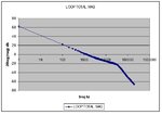
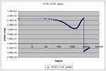
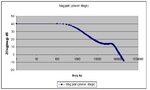
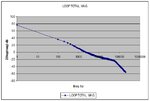
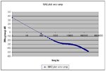
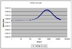
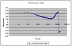
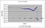
Please find attached the gain and phase Bode plots for a buckboost LED driver.
Vin = 10
Iout= 0.5A
Fsw = 70.4KHz
Constant off time

Please advise,do the Bode plots look right?
 

Attachments

  • bukboost111.pdf
    33.1 KB · Views: 38
  • mag vs freq.jpg
    mag vs freq.jpg
    40.6 KB · Views: 49
  • phase vs freq.jpg
    phase vs freq.jpg
    55.8 KB · Views: 54

It seems strange that your phase boosts so much above your crossover frequency... is this the response of the entire loop? It would be easier answer if you separately presented the response of the error amp and the response of the converter itself.
 
  • Like
Reactions: treez

    T

    Points: 2
    Helpful Answer Positive Rating
It would be easier answer if you separately presented the response of the error amp and the response of the converter itself.

thankyou, though it won't let me attach excel documents.
One thing is , as per the schematic, I "biased" up the current sense voltage...and for the current sense resistor value, I just used 0.12 Ohms (R1) in the calculation...I wonder if this is right?
Also, since the LT1243 has a 3:1 divider in it, I put in the gain of x 0.33, I wonder if this also is right or wrong?

- - - Updated - - -

Actually , ive shortened the off-time and changed the inductor down to 47uH so that I can make the compensation capacitor , C3, smaller, and still have good gain and phase margin.
Having a large value for C3 makes it start up too slowly, which I don't want, because this is for a flash lamp which flashes on and off 80ms ON, 40ms OFF...etc etc
Here are all the bode plots and the new schematic. (+ corresponding LTspice simulation)

Fsw is 119KHz with the new lower off time of 1.83us.
 

Attachments

  • bukboost.pdf
    33.2 KB · Views: 41
  • bukboost.txt
    9.6 KB · Views: 35
  • Error amp _mag plot.jpg
    Error amp _mag plot.jpg
    43.7 KB · Views: 91
  • Error amp _phase plot.jpg
    Error amp _phase plot.jpg
    41.2 KB · Views: 99
  • Power stage _Mag plot.jpg
    Power stage _Mag plot.jpg
    35.9 KB · Views: 87
  • Power stage _phase plot.jpg
    Power stage _phase plot.jpg
    41.6 KB · Views: 82
  • Total loop _mag plot.jpg
    Total loop _mag plot.jpg
    40.3 KB · Views: 86
  • Total loop _phase plot.jpg
    Total loop _phase plot.jpg
    53.9 KB · Views: 82

Status
Not open for further replies.

Similar threads

Part and Inventory Search

Welcome to EDABoard.com

Sponsor

Back
Top