Continue to Site

Welcome to EDAboard.com

Welcome to our site! EDAboard.com is an international Electronics Discussion Forum focused on EDA software, circuits, schematics, books, theory, papers, asic, pld, 8051, DSP, Network, RF, Analog Design, PCB, Service Manuals... and a whole lot more! To participate you need to register. Registration is free. Click here to register now.

DIY ESR Meter and Capacitance meter

Status
Not open for further replies.

vsmGuy

Advanced Member level 2
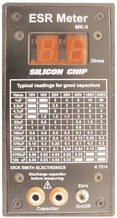
Joined
Jun 26, 2006
Messages
503
Helped
44
Reputation
88
Reaction score
15
Trophy points
1,298
Location
VddVss
Activity points
3,882
diy esr meter

I got these links for DIY ESR meter :

**broken link removed**

But don't know how they really might perform. Anyone built these ?
I am really looking for a reliable DIY ESR meter. The ones available are not realiable at all.

I am also looking forward to building a capacitance meter (my DVM has till 200uF)
so I can read atleast till 4000uF

Any links or ideas ?
 

esr meter diy

The Elektor ESR meter looks good:


FoxyRick.

P.s. try using the 'Search' function - you can find a lot of stuff here if you do.
 
diy capacitance meter

FoxyRick said:
The Elektor ESR meter looks good:

h**p://
h**p://

FoxyRick.

P.s. try using the 'Search' function - you can find a lot of stuff here if you do.

Actaually I had my minds fixed on building either of the links I had posted, but thanks anywyas.

What I am really looking forward to is a ESR Meter that someone REALLY built and can vouch for it's performance.
 

Re: diy esr meter

vsmGuy said:
I am really looking for a reliable DIY ESR meter. The ones available are not realiable at all.

I am also looking forward to building a capacitance meter (my DVM has till 200uF)
so I can read atleast till 4000uF

Any links or ideas ?

I just posted info about project like the one you're looking for:
 

    vsmGuy

    Points: 2
    Helpful Answer Positive Rating
LCFesR 3.05 unit is a precise, wide range LCF and ESR meter that is to say it measures inductivity (L), capacity (C), frequency (F) and equivalent series resistance (ESR) of a capacitor inside an electronic circuit (in-circuit). The meter can be easily built with homemade one- or double-sided PCB and available electronic components. It's functions are base on an ATMega8-16PU or an improved ATMega88PA-PU microprocessor.

By following the project you can build one but if you get inspired, you can use the information, circuit schematic to make your own from scratch.

**broken link removed**
 
Last edited:

It is a nice project, Hutale, no doubts, but IMHO it is not very ethic to self-advertise your own web-site, especially considering fact you're going to charge $ for the firmware. Let others do the choice.

BTW, vsmGuy, R2-D2 released his new project as promised (and his firmware is absolutely FREE).
New meter includes:
1. Well-known LC meter based on LM311 with extended range (up to 1-2mkF) and precision. Uses fast PIC18F2520 CPU running at 40MHz.
Uses some his own "know-hows" to insure proper self-calibration over extended period of time and swamping any stray capacitance/inductance.
2. Also it does have C/ESR meter part for Caps ranging over 0,1mkF up to 600000 mkF, and R/ESR up to 100 Ohms.
3. Also the meter has Frequency Input for up to 50MHz without presacaler and up to 9,9GHz with prescaler (max F depends only on prescaler - you can use any you can find in your junkbox).
4. Using Graphic LCD from Nokia 3310 cellphone or any other compatible with Philips PCD8544 chipset. And the graphics is amasing - best I've seen so far for DIY project.

Here is the link: -> RLC -> ESR/R/L/C/F meter (by R2-D2) (sorry, not yet translated into English).
Schematics is in SPlan7 format and PCB is in SprintLayout5 format, freeware versions of the software to see them available here:
Sprint-Layout sPlan

Right now I'm building his new project (I'm designing my own PCB and bit different schematics) so do the others guys on VRTP.ru forums. This is ongoing and exciting new project...
 
  • Like
Reactions: vsmGuy

    vsmGuy

    Points: 2
    Helpful Answer Positive Rating
I do not want to argue. As for my project every one has choice too. I got feedback that some students could use information from the project and started his own's, so it can be useful for ones.
 

Having had the personal experence of using the LCFesR meter I will give my input.

1st. Being a student trying to re-learn electronics from 20 years ago to save anyway we can is important. $60us delivered seemed like a good deal at first.

1.) The PCB board seems to be home made, not one imprint of what is going where. Only a graphic is available for placement of componants.

2.) The headers provided do not fit in the board. Have to use ribbon cable. That breaks with the slightest move and requires re-soldering on the board and LCD.

Would have been nice to have the riser to just plug in and out. But the pins are not lined up so riser and straight plub in would not work, would still need ribbon cable or other wire.

3.) Then if you remove something more than once or twice, you have to fix traces. To replace board from him is $30 w/Atmega chip, in the states it's $10 but can't get gerber files to have any made up. Then if you need to re-do Atmega chip you can't. Have to purchase from him. The chip is $5 in the states.

4.) Selector switch is not high enough above the capasitors to be able to bolt properly in the box. Was told to just use it that way, it would be fine. It uses the board to hold in place. This will stress the board after a while.

5.) Talked with teacher and was told it was a waste of money and I was on my own with it.

I hope to get another built as soon I find one a little more student friendly.
 

Brosskgm, now I do not believe you are student (I realized that you work for or have a Services - your Paypal address says this). You have just bought one KIT, have tested it and tried to get only negatives. You can do this but be correct. I'd like to answer:

1. PCB board is made by professionals. Yes it does not have imprint because I do not want it to be made (it'd be more expensive) but with nice pictures anyone can assemble it well (you did it, did you?)

2. The holes of LCD header is 0.8mm for use of ribbon cable. Someone likes to use it but if others likes to use header, just drill some holes with 1 mm drill and it will be OK (I can do it in 3 minutes).
I argue that ribbon cable breaks with the slightest move. Ribbon cable is used well in many computers and meters. If the meter is boxed, ribbon cable will not break. Meter is to be used, not assemble and disassemble, as you do every day in your Services. If you want to assemble and disassemble, you can make your own PCB for that.

3. Why should we have to remove something more than once or twice? Yes, you speak as a Service. I had done this lots of times when developing the meter but did not have to fix traces. Traces and PINs are big enough so soldering is easy.

4. You are wrong, just read again my offer in my e-mail and ask for my forgiveness: 30 $ is for PCB + ATMega88PA-PU with software burn in it (PCB is only 6$). Yes I ask some $ for my hard programming work and you can not re-programm the processor - you can not copy meters, just assemble and use one that you bought.

Selector switch is soldered to PCB board with 15 PIN, so it's strongly soldered to PCB and is used like that. It is a Lorlin UK professional selector switch.

5. The meter is for hobby who like to cheaply build one that works well for it is made. My video is a proof of it.

As to PCB anyone can see the assembled PCB in my webpage and make own judgement.

So again I do not want to argue, only want a correct opinion.
 
Last edited:

Yes, I am student. My paypal is for the things I sell on ebay that have nothing to do with electronics. So go ahead call me (Youi have my number) since you think you know so much or want to make your self look correct. I'm 53 and I'm a student again having to re-learn electronics repair that I dropped out of 20 years ago becuse of the PC clone era. I wanted to try and build all my test equipment, but should have settled on the Blue meter for $79.

Justin also knows I'm a student, since I'm also learning from him. Ask him. Don't have to listem to me. I've only been at this for about a month now.

1.)
I did assemble after you told me I had to clip legs of some of the provided item, don't have the 1mm drill or way to get one. Can't find the knob for the switch since we don't have a place you told me to pick one up at. The board corners would have to be drilled out to mount unless you have small 1mm screws.

When you move the compnant the trace pops off plain and simple. Solder sucker pulled it right off the board.

They are $10/ea here in states with imprint.

2.)
When they are not yet in a box, and are wiggled around, they break, then they have to be un-sodlered to work with. Headers would have been nice, you even said in an email you decided to make the holes bigger for this since you actually provide them in the kit.

3.)
It's only disassembled because it did not work and when I plugged another LCD in it, (That I also emailed you about) it gave me squares. How else do you test the LCD if you don't put another in it place. I don't know how to do that yet.

Then I had to pull the 22ga wire I wanted to use because you told me one might have been broke. They weren't. But that ribbon was better.

Then had to put the cable in. But then since it didn't light up the 1st time turned on, the 1st time screen was never seen. Then when I told you I got wording on it that it's stuck on esr <30 ohm in any selction you decided not to support it any longer.

4.)
$30 with chip is what I said and what you said. I did not miss quote that.

Yes your email "Quote
Yes, I have some PCB boards and programmed Atmega88PA-PU IC-s as well
as complete packages
(members.upc.hu/lethanh.hung/LCFESRmero/en/) on sell, if you
are interested in:

1 PCB board + 1 programmed Atmega88PA-PU IC : 30 $ + postage
or
1 Complete package: 55 $ + postage

I did not miss quote anything that happened.
 

We had exchange lots of e-mail and I tried to help until now but suddenly you wrote negative things here without asking my help. I always helped, remember! I do not know what to think. I'm sure that my KIT is OK, lots of electronic services assemble and use successuly. Yes for them and for me too 1, 2 mm drills are at hand. So you get problem, I think we can solve it together. Now I'm sure the problem is because of your soldering skill. I know how to test LCD and processor without useing PCB. But not here, we should continue in private e-mail.
 

I did. You are responding quicker here than by email. I sent an email that I must have done something wrong or what ever, and that all I get is froze on ESR <30 ohm on any selection and then another that it's solid squares on the LCD and now that all it does is flash when the leads are put together, and your LCD is not doing anything and you now only respond that all I had to do was ask, but you still have not responded to those messages.
 

Thanks everyone for your help. hutale helped me get it working. All I have top do now is find a chart so I understand if a cap is good or bad.

A new 100uf 16v gave me an esr of 893 m(Ohm)
A new 4.7uf 25v gave me ESR 13.52 Ohm

Is there a chart available on ESR?

Thanks
 

I have found some charts in Internet. Such charts should be used only as information guide, because ESR values depend on manufacturer, measuring techniques, and measuring frequency (especially capacitors of small capacity show more difference because they easily charge even under some us). So different meters may measure different ESR values but each can be consistent for itself that is the difference in value beetween good and bad capacitor is clear and the bad one can be easily detemined. It's recommended that everybody makes his own chart.

12_1292098222.jpg
 

Yes I ask some $ for my hard programming work and you can not re-programm the processor

Does this mean if I flash my own Atmega with the demo code I can't re-program it for other projects?

Also, how much are you charging for the unlocked software?
 

Yes I ask some $ for my hard programming work and you can not re-programm the processor

We should read all the text to not misunderstand what the sentence means. From the text it means: by trying reading and useing the content of the processor got from me one can not re-program the processor, neither other processors - it's simply because it's content is copy-protected by processor itself so copying is not available.

Does this mean if I flash my own Atmega with the demo code I can't re-program it for other projects?

Also, how much are you charging for the unlocked software?
No, it does not! Any AtMega burnt with any software can be erased to be reused for any projects (even the processor got from me can be easily erased too). DEMO software can not be unlocked, it's such! I think cost of full software version should be asked in private mail.
 
Last edited:

No, it does not! Any AtMega burnt with any software can be erased to be reused for any projects (even the processor got from me can be easily erased too).
Thanks for clarifying.
I'm a noob to these mcu based projects.
 

Would have been nice to have the riser to just plug in and out. But the pins are not lined up so riser and straight plub in would not work, would still need ribbon cable or other wire.

By having your suggestion I have modified the PCB so now a 14 PIN ribbon cable father connector is to be soldered to PCB and LCD display can be connected easily to PCB by using 14 PIN ribbon cable mother connector. You can see it on pictures of assembled PCB:

**broken link removed**

Thank you for your suggestion!
 

Hi!
Can somebody please tell me the last information about the project of R2-D2 (I don't understand Russian, nor google-translate help much):
1) What are a) Measurement type that instrument can handle (L, C, F...);
b) Ranges; c) Maximal resolutions for each mode (especially mΩ's); d) Accuracies.
2) Can it measure internal resistance of batteries?
3) Can it measure parasitic capacitance of an inductor?

Do you know is it possible to order programmed PIC from author (and eventually other critical components) from author
and for what price?

TIA! (Sorry for my uuugly English)!
 

Just over $65 US last year.

I tried this unit. 1st time I was a bit too hot and ordered a second PCB board. Then it was running perfect. Then I turned it up about 6 month's later because someone was interested in purchasing it. It read one capacitor and died. Author said because of previous hot solder problem not related to this PCB was the cause. So then he told me to order a new PIC for it and program the trial version. The only part that did not work on the unit was ESR. All the others worked fine. So I tossed it as not usable.

All and all. When it worked fine for a few weeks during class. But I guess sitting might have had something to do with it. Must have caused the new board to go bad because of old board soldering.
 

Status
Not open for further replies.

Part and Inventory Search

Welcome to EDABoard.com

Sponsor

Back
Top