Continue to Site

Welcome to EDAboard.com

Welcome to our site! EDAboard.com is an international Electronics Discussion Forum focused on EDA software, circuits, schematics, books, theory, papers, asic, pld, 8051, DSP, Network, RF, Analog Design, PCB, Service Manuals... and a whole lot more! To participate you need to register. Registration is free. Click here to register now.

Distortion in single phase inverter

Status
Not open for further replies.

fadhel93

Newbie level 4
Joined
May 19, 2015
Messages
7
Helped
0
Reputation
0
Reaction score
0
Trophy points
1
Activity points
59
Greetings.
Trying to make a sine wave inverter.
Sinusoidal PWM, an mbed driving an H-bridge with two IR2186 at 20KHz

gate.jpg

gate1.jpg
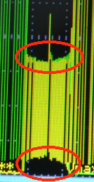
the outputs from the mbed are clear half sinewaves but the output without the filter has distortions every cirtain time
DSC_1291.jpgDSC_1292.jpg


(the code)


Code C - [expand]
1
2
3
4
5
6
7
8
9
10
11
12
13
14
15
16
17
18
19
20
21
22
23
24
25
26
27
28
29
30
31
32
33
34
35
36
37
38
39
40
41
42
43
44
45
46
47
48
49
50
51
52
53
54
55
56
57
58
59
60
61
62
63
64
65
/*
*********************************************************
*               Fadhel Ali 201102569                    *                                      
*                  DC to AC Inverter                    *
*********************************************************
*/
#include "mbed.h"
#include "QEI.h"
#define size 512
#define ph50Hz 4400
#define pi 3.14159265


PwmOut out(p21);
PwmOut out1(p22);
PwmOut out2(p23);
PwmOut out3(p24);
QEI wheel (p15, p16, NC, 16);
DigitalIn  switch1 (p19);
DigitalOut base(p30);


int main() 
{
    out.period_us(50);
    
    float sin1[size],sin2[size],sin3[size],sin4[size];
    float omega;
    int x=0;
    int y;
    int n, z=0;
    base = 0;
    
 
        for (int i=0; i<size; i++)
    {
        //fill the arrays with the sine wave's amplitude values
        omega= 2*pi*i/float(size); 
 
        sin1[i]=(sin(omega));//half-wave rectified signal     
        sin2[i]=(sin(omega+pi));//180 deg phase so each phase will not work togother       
        sin3[i]=(sin(omega));    
        sin4[i]=(sin(omega+pi)); 
        
 
    }
   wheel.reset();
 
    n=ph50Hz;
      
       
    while (1)
    {
    z=wheel.getPulses()*100;   //read the state of the shaft encoder
    x+=n+z;
    y=(x>>14) & (size-1);  //controls the frequency
    //call the sine wave arrays
    out=sin1[y];   
    out1=sin2[y];
    out2=sin3[y]; 
    out3=sin4[y]; 
    }
}


what could be the problem
 
Last edited by a moderator:

thank you for replying,
its a resistive load, about 17watts
 

yes in the DC to DC converter, there are some ripples. but I checked the dc to dc converter seperatly and it was fine withoud any voltage drop or regulation but only when it is connected to the h-bridge the voltage drops.
 

See the circled areas below. The mosfets are not fully turning on or off during those parts of the cycle.


The switching is too rapid for them to act. This is typical of parasitic (high-frequency) oscillations.
 

Status
Not open for further replies.

Part and Inventory Search

Welcome to EDABoard.com

Sponsor

Back
Top