Continue to Site

Welcome to EDAboard.com

Welcome to our site! EDAboard.com is an international Electronics Discussion Forum focused on EDA software, circuits, schematics, books, theory, papers, asic, pld, 8051, DSP, Network, RF, Analog Design, PCB, Service Manuals... and a whole lot more! To participate you need to register. Registration is free. Click here to register now.

Discrete SMPS using saturating transformer?

cupoftea

Advanced Member level 5
Joined
Jun 13, 2021
Messages
2,611
Helped
54
Reputation
108
Reaction score
115
Trophy points
63
Activity points
13,687
Hi,
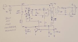
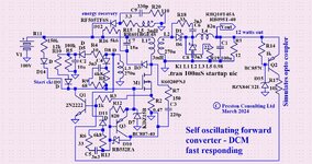
Has anybody any familiarity with any kind of discrete one transistor forward using no control chip?
We have been sent one to modify. Its useless, and would best have been done as a bog standard flyback, but i cant
show schem. It doesnt work on the LTspice simulator so i believe the transformer must be going in and out
of saturation (deliberately).
 
I wouldn't say "familiar", but I have been told that as recently
as the '80s the Trident missiles used mag-amps and some
sort of discrete bodge to control them, as the power modulator.
At the time there were no nuclear-event-survivable power devices
(according to the people who tested everything that they could
find).

Now your systems that have to deliver efficiency (not much of a
concern for a one-use thermal battery) might find the mag-amp
"saturating control current" wasteful. But it was a done thing, by
folks who had no better option.

I imagine that for any kind of luck simulating, you would need a
"core and winding" transformer model (not L and M), with the
saturation well fitted. That's extra effort for an element which is
usually "don't do that!". But maybe you can find mag-amp
vendor or contrib models?
 
post schematic please - hand drawn and photo off phone, there are such designs floating about, usually they are a compromise - as soon as one component starts to go off ( usually an electro ) they tend to fail.

Is is CCM or CrCM or DCM ?

you can of course use a TLC555 as a controller without too much fuss
--- Updated ---

Vin ? Vout ? power ?
--- Updated ---

1712093301250.png

Here is a typ ckt, note the Tx must saturate for turn off to happen - this one has no feedback to control Vout
--- Updated ---

p.s. - if the equipment has been made and sold - then it is in the public domain and you can post the sch.
 
Last edited:
i believe the transformer must be going in and out
of saturation (deliberately)
This brings to mind the 'joule thief' design which has gotten some attention.

bigclive.com
re-introduced this to the public.

I've read it has the name 'blocking oscillator'. Works from a transistor and transformer behavior. Bias conducts in one winding, collector current in the other.

The windings conduct only as long as one is changing. When one winding reaches maximum it stops changing. They both turn off (I'm not sure how much one winding is saturated). The bright white led flashes briefly as the inductive charge is enough to illuminate it.

This system works off a cell which is depleted to as low as 0.7V. It's a type of step-up oscillator that attracts attention to build projects made to extract remaining power from a low cell.
 
Here you go, self osc fwd converter, no saturating Tx ( unless you design it wrong ), pk curr limited on the pri side providing o/p curr limit also,

volt reg as well: @cupoftea
 

Attachments

  • self osc fwd conv.jpg
    self osc fwd conv.jpg
    233.5 KB · Views: 42
I have an improved version of the above - but with rather more parts to give; cleaner FET switching, a measure of slope comp, narrower switching freq range and regen return of Imag to the input - for improved efficiency.
 
Thanks Easy Peasy, its not the one i have here, but interesting all the same
Ours is 12Vin, 13.5Vout, 39W out, with another version (hopefully can be same except for sense res) required for 32Vin and 13.5Vout (but thats just one amp).

The circuit is only of sentimental value, and should have just been done as a bog standard control chip Flyback type...but it has "sentimental" value to the external customer. So i cant show the schematic, even though no-one in their right mind would copy it.

I do have it working on the LTspice now......but the exact actual schem values are not (yet) gotten working.

We do have, as is probably expected, the source sense switching the NPN....so that bits the same.
Bias coil has no rectifier diode.
There is no clamp or snubber across the primary coil whatsoever.
I believe the aux coil is actually helping to reset the transformer....though its not the typical 1TF reset winding.

There are three RC time constants on pri side.

One is the RC from the bias coil to the FET gate
Also, another NPN on the FET gate but fed by 22k and 2n2 to ground...

Another RC time constant which seems to be something to do with transient management.

There is actually a TL431/OPTO on the sec side.
 
Last edited:
I have an improved version of the above - but with rather more parts to give; cleaner FET switching, a measure of slope comp, narrower switching freq range and regen return of Imag to the input - for improved efficiency.

Thanks, This discrete SMPS . like most of them, suffers from the use of the Vbe as the current sense reference, and for other references, which makes it horrendously susceptible to tolerance effects with batch and temperature. One for the bin....though i have seen some others, with other discrete ccts in there to try and fight the tolerance issuse.
 
Well, there are improvements, if the pk curr is effectively in a feed back loop - there are less issues:

I saw this today on LinkedIn: looks promising
 

Attachments

  • self osc fwd conc DCM ref.JPG
    self osc fwd conc DCM ref.JPG
    302.3 KB · Views: 36
  • Vout SO fwd start.JPG
    Vout SO fwd start.JPG
    157.8 KB · Views: 36

LaTeX Commands Quick-Menu:

Similar threads

Part and Inventory Search

Welcome to EDABoard.com

Sponsor

Back
Top