Continue to Site

Welcome to EDAboard.com

Welcome to our site! EDAboard.com is an international Electronics Discussion Forum focused on EDA software, circuits, schematics, books, theory, papers, asic, pld, 8051, DSP, Network, RF, Analog Design, PCB, Service Manuals... and a whole lot more! To participate you need to register. Registration is free. Click here to register now.

Discrete negative to positive voltage converter?

Status
Not open for further replies.

neazoi

Advanced Member level 6
Joined
Jan 5, 2008
Messages
4,119
Helped
13
Reputation
26
Reaction score
15
Trophy points
1,318
Location
Greece
Activity points
36,918
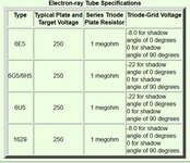
Magic eye vacuum tubes required negative voltages on their grids, usually derived from the receiver circuits (https://www.radioremembered.org/tuneye.htm)

That is:
0V to indicate minimum signal
-21V to indicate maximum signal

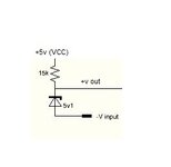
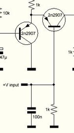
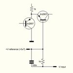
I am trying to find a way to convert such a negative voltage to a positive one.
That is:
0v to indicate minimum signal
+5v (or greater, no problem I can scale it down with a potential divider) to indicate maximum signal

Is there any simple discrete way to do this?
 

Attachments

  • Capture.JPG
    Capture.JPG
    62.3 KB · Views: 120

For what purpose?
I'm asking because the simplest method is to add a Zener diode and a 'pull-up' resistor to a positive voltage so the top of the diode is Vz higher than the negative voltage you want to measure. However, if this is to retro-fit to an ancient receiver, the current through the diode may upset the AGC line it is monitoring. Consider the AGC voltage normally fed the control grid of amplifier stages where the current load was negligible.

Brian.
Can you please let me know how to wire up this setup with the zenner Brian?
A resistor from +5v to the anode of the zener and the cathode of the zener to the ground?
Where to take the positive voltage out for the measuring circuit?
--- Updated ---

Can you please let me know how to wire up this setup with the zenner Brian?
A resistor from +5v to the anode of the zener and the cathode of the zener to the ground?
Where to take the positive voltage out for the measuring circuit?
I think I have figured this out, am I correct?

I used a 5v1 by random, what do you propose?
I am not sure of how the circuit works...
--- Updated ---

Can you please let me know how to wire up this setup with the zenner Brian?
A resistor from +5v to the anode of the zener and the cathode of the zener to the ground?
Where to take the positive voltage out for the measuring circuit?
--- Updated ---


I think I have figured this out, am I correct?

I used a 5v1 by random, what do you propose?
I am not sure of how the circuit works...
If I replace the zenner with a resistor, I get the same effect.
 

Attachments

  • Capture.JPG
    Capture.JPG
    14.1 KB · Views: 202
Last edited:

You can use 3 resistors to scale a - V to positive (in some cases just 2 R's) -

1643067221227.png


See attached spreadsheet.

Zener approach has advantage no G loss in translated signal, whereas if one wants
to compress and offset a signal R divider better approach. But as you can see the Vref has
to be higher than peak Vout.....


Regards, Dana.
 

Attachments

  • TI Voltage Divider.zip
    302.3 KB · Views: 162
Last edited:

You can use 3 resistors to scale a - V to positive (in some cases just 2 R's) -

View attachment 174090

See attached spreadsheet.

Zener approach has advantage no G loss in translated signal, whereas if one wants
to compress and offset a signal R divider better approach. But as you can see the Vref has
to be higher than peak Vout.....


Regards, Dana.
Yes Dana it worked indeed. It is only that it has the opposite behaviour. I need
0V to indicate minimum signal
-21V to indicate maximum signal

With this potential divider it is the other way round. Is there a way to fix this?
Perhaps with the addition of a transistor inverter which will also provide isolation of the input (i.e. DC not flowing towards the input)?
 

Attachments

  • 1643076951537.png
    1643076951537.png
    95.1 KB · Views: 94
Last edited:

I need
0V to indicate minimum signal
-21V to indicate maximum signal
...
Perhaps with the addition of a transistor inverter which will also provide isolation of the input (i.e. DC not flowing towards the input)?

JFET bias is voltage-controlled. Input resistance can be very high. The tiniest current flows.
By taking output from the upper leg, it inverts polarity.

jfet inverts 0V to neg 20V makes output 0V to 5V.png
 

JFET bias is voltage-controlled. Input resistance can be very high. The tiniest current flows.
By taking output from the upper leg, it inverts polarity.

View attachment 174094
Shall I try this circuit including the addition of Dana's potential divider/shifter or standalone?
I guess a symmetrical PSU is needed, or it can be done without it?
 

Hi,

to me it´s not clear
* whether you want a signal just "shifted" from negative to positive ...
* or want it to be inverted.
* or both

Better say:
* minimum input voltage --> output voltage
* maximum input voltage --> output voltage

As an example:
input min: 0V --> -8V out
input max 5V --> -21V out
which could be mathematically expressed as : output = - input * 13 / 5 -8
assuming linear charactereistic.

Klaus
The needed behaviour is:
0V to indicate minimum signal
-21V to indicate maximum signal

My meter as it is now requires:
0v to indicate minimum signal
+5v (or greater, no problem I can scale it down with a potential divider) to indicate maximum signal

So in both cases, 0v indicates minimum signal.
An input to the "converter circuit" of -21v, must output +5v.
If this is so , my meter will be fully deflected with an input of -21v to the circuit
 

Hi,

so:
* 0V input --> 0V output
* -21V input --> +5V output

This is inverting behaviour! I doubt this can be accomplished with passive circuitry.

How I´d do it: (You are free to go your own way)
OPAMP, 2 resistors.

Klaus
 

Hi,

so:
* 0V input --> 0V output
* -21V input --> +5V output

This is inverting behaviour! I doubt this can be accomplished with passive circuitry.

How I´d do it: (You are free to go your own way)
OPAMP, 2 resistors.

Klaus
Exactly. Actually the +5v can be +300mV or so. I am bringing this down to 300mv with a potential divider after all. I am telling you that so as to show that there is no problem presenting any maximum positive voltage, as long as it exceeds +300mv

I built the circuit above with the JFET but It did not work, I do not know why. Can it be done with a single transistor instead of an opamp? I know a single transistor can be used as an inverter in digital circuits, but I am confused with these negative voltages.
I would really like the inverter circuit not to require a negative VCC to operate.
 
Last edited:

Yes Dana it worked indeed. It is only that it has the opposite behaviour. I need
0V to indicate minimum signal
-21V to indicate maximum signal

With this potential divider it is the other way round. Is there a way to fix this?
Perhaps with the addition of a transistor inverter which will also provide isolation of the input (i.e. DC not flowing towards the input)?
I think you can do this with Case 3 in the TI ap note posted, eg. single supply, 5V,
using a RRIO OpAmp. Design procedure is there.

Regards, Dana.
 

Ok, this might work (or not...)
The initial meter circuit is at the first picture. It needs a 0 to +5v at the +vinput.

Now how about converting it to that of the second picture? instead of connecting the input circuit to the ground, to connect it to the -v input (0 to -21v). I think there must be a reference voltage present so I tied the other terminal to +5v.

Now, all the transistor cares is to see a positive voltage at it's base, that is +5v at the top of the 1k and 0v at it's bottom. Now, if we instead increase the negative voltage at the bottom of the resistor, won't it be the same voltage difference there?

I might be talking nonsense so excuse me if so.
--- Updated ---

I think you can do this with Case 3 in the TI ap note posted, eg. single supply, 5V,
using a RRIO OpAmp. Design procedure is there.

Regards, Dana.
It seems ok, although it uses an opamp and I preferred discrete. But if I could use a general purpose opamp, I could go for it. I guess any opamp could work with this.
 

Attachments

  • 1.jpg
    1.jpg
    16.5 KB · Views: 109
  • 2.jpg
    2.jpg
    17.5 KB · Views: 107
Last edited:

Hi,


as Dana wrote: RR IO OPAMP = Rail-to-Rail Input and ouput OPAMP.

Klaus
Pick a RRIO 5V OpAmp, and keep fdbk R high as RRIO OpAmps lose
RRO characteristic as you load them down.

Your discrete circuit, where you place a Vref source tied to base of output PNP, since you terminate
base in a V source your - Vin has no effect on the PNP.


Regards, Dana.
 
Last edited:

Below is the LTspice simulation of one circuit using two BJT's and the other using a CMOS rail-rail opamp, both operating from a single 5V supply.
Do those do what you want?

1643125758985.png
 
  • Like
Reactions: danadakk

    neazoi

    Points: 2
    Helpful Answer Positive Rating
Below is the LTspice simulation of one circuit using two BJT's and the other using a CMOS rail-rail opamp, both operating from a single 5V supply.
Do those do what you want?

View attachment 174099
Your discrete circuit worked ok!
It is only that it is quite insensitive, so no big deflection. I wonder what values of resistors shall I tweak to make it more sensitive?
I used 2n2222 and 2n2907
--- Updated ---

Your discrete circuit worked ok!
It is only that it is quite insensitive, so no big deflection. I wonder what values of resistors shall I tweak to make it more sensitive?
I used 2n2222 and 2n2907
I found it. just vary the emitter resistor of the pnp transistor to change its sensitivity.
The circuit works like a charm, thanks a lot!

If you set the emitter resistor of the pnp transistor so that there is full deflection at -21v, then minimum deflection starts from -6v and not 0v.
Any ideas how to fix this somehow?
 
Last edited:

Any ideas how to fix this
How about this:
I added D1 and D2 to reduce the start offset to <1V and tweaked the resistors to give about a 3V output span, which I think is about as good as you can get with that circuit.
If you want a greater span that starts at 0V, you will likely need to go to the simpler opamp circuit.

1643145977629.png
 

How about this:
I added D1 and D2 to reduce the start offset to <1V and tweaked the resistors to give about a 3V output span, which I think is about as good as you can get with that circuit.
If you want a greater span that starts at 0V, you will likely need to go to the simpler opamp circuit.

View attachment 174108
Yes this reduced the min voltage on my prototype to -3.3v (from (-6v that was before) whereas at the same time achieved a maximum at -22v.
Great improvement!

If R4 is changed to 10k, minimum is -1.94v. At 1k, min is -1.65v
And if I add a third diode, it goes down to -0.9v
These are all for maximum range at -22v.
I will keep experimenting more but if you have any ideas for further improvement, please let me know.

With these values, I sense a nice logarithmic response of the meter, which might be good as a tuning indicator.
--- Updated ---

I noticed that in your circuit, I had to place 5 diodes in series in order to bring the min voltage to -1v (at full range).
I wonder if there is a better way to do it instead of using 5 diodes?
 
Last edited:

Status
Not open for further replies.

Similar threads

Part and Inventory Search

Welcome to EDABoard.com

Sponsor

Back
Top