Continue to Site

Welcome to EDAboard.com

Welcome to our site! EDAboard.com is an international Electronics Discussion Forum focused on EDA software, circuits, schematics, books, theory, papers, asic, pld, 8051, DSP, Network, RF, Analog Design, PCB, Service Manuals... and a whole lot more! To participate you need to register. Registration is free. Click here to register now.

Discrete negative to positive voltage converter?

Status
Not open for further replies.
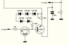
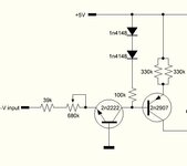
Are all your resistor values the exact same as in my simulation in post #19?
YEs, apart from the collector one which is 1k (shared with the positive input circuit)
If that matters then I can alter the input circuit.
 

Attachments

  • Capture.JPG
    Capture.JPG
    22.7 KB · Views: 77

YEs, apart from the collector one which is 1k (shared with the positive input circuit)
If that matters then I can alter the input circuit.
Of course it matters.
It determines the gain of the second stage.

If your results are significantly different from my simulation, then check your circuit.
 

    neazoi

    Points: 2
    Helpful Answer Positive Rating
I would really like the inverter circuit not to require a negative VCC to operate.

Simple method to lift a negative voltage into the positive range 0-5V. Potentiometer selects a midway position between your incoming signal and supply +6.6 V.

potentiometer lifts signal 0 to -20V up to 0-5V.png
 

    neazoi

    Points: 2
    Helpful Answer Positive Rating
Simple method to lift a negative voltage into the positive range 0-5V. Potentiometer selects a midway position between your incoming signal and supply +6.6 V.

View attachment 174112
This is very interesting too!
If curtschow circuit did not work I would try it.
The only problem I see with it, is isolation. DC is allowed to flow to and from all 3 terminals of the potentiometer. That might disrupt other circuits connected to the input line (the control line) in a receiver.

Saying so, I find a tendency to oscillate in curtschow circuit. At low input voltages, the output voltage is not stable like the input is, but it tends to go up and down a few milivolts, which causes the display to deviate a bit up and down.

I still haven't tried to change the collector resistor to 10k (I will do this later) but can I do something to fix this?
 

Most simulations and circuit suggestions seems to ignore the high source impedance (1 MOhm) of AGC voltage. The JFET inverter circuit is the circuit idea that has potentially a sufficiebt input impedance, except for the 1 M pot which should be replaced by a voltage divider with higher impedance.

Do I understand right, that an auxiliary negative power supply like -5V in post #7 can be provided?

The circuit in post #19 has an input resistor of 1Meg, it should load down the AGC very little, isn't it?

No a negative power supply is not available (post #7). I would only consider this if there is no other way it can be done. However this jfet circuit did not work for me on tests for some reason, whereas the one in #19 worked perfectly.

I just noticed though (#19) a tendency to "oscillate". At low input voltages (max sensitivity), the output voltage is not stable like the input is, but it tends to go up and down a few milivolts, which causes the display to deviate a bit up and down.
--- Updated ---

Saying so, I find a tendency to oscillate in curtschow circuit. At low input voltages, the output voltage is not stable like the input is, but it tends to go up and down a few milivolts, which causes the display to deviate a bit up and down.

I still haven't tried to change the collector resistor to 10k (I will do this later) but can I do something to fix this?
I tried replacing that 1k collector resistor at the second stage of your circuit to 10k.
Indeed, now it needs only 2 diodes to go down to 600mv.
However this variation in the output voltage (variation/oscillation) is much greater.
It seems having so much gain is not good.

I am thinking of replacing the collector resistor at the second stage of your circuit to 100 ohms or so, so see the difference.
 
Last edited:

I just noticed though (#19) a tendency to "oscillate".
The circuit is very simple with no feedback, so I doubt that it is oscillating.
You are likely just seeing some input variation which is amplified by the circuit.
What is the frequency of this deviation?
am thinking of replacing the collector resistor at the second stage of your circuit to 100 ohms or so, so see the difference.
Well, that will reduce the output voltage span along with the deviation.
 

The circuit is very simple with no feedback, so I doubt that it is oscillating.
You are likely just seeing some input variation which is amplified by the circuit.
What is the frequency of this deviation?

Well, that will reduce the output voltage span along with the deviation.
Yes, I tested it and it is better to have the resistor to 10k (with 2 diodes like you said).
Oscillation frequency (much more pronounced with the 10k resistor) is something like 1-2Hz. If I had an analogue multimeter I could tell you the voltage value ends, but my digital multimeter cannot catch up with this rate
 

If I had an analogue multimeter I could tell you the voltage value ends, but my digital multimeter cannot catch up with this rate
So I assume you don't have an oscilloscope to look at the signal(?)

What do you read with the meter set to measure AC?
 

So I assume you don't have an oscilloscope to look at the signal(?)

What do you read with the meter set to measure AC?
I found the source of instability. The gain of the PNP needed to be set at minimum by setting the emitter of the PNP with a 165K. It's collector is tied to ground with 10k.
Now that I found a stable point, I can set the gain by varying the input resistor. It is not the best way, but it is independent of the rest of the circuit. With these resistors, it provides a minimum isolation of 39k and a maximum of 560k depended on the gain setting. Most of the times this will replace devices that need maximum range, so the isolation will be in the range of a few 100s of k.
The 100k in place works ok and it provides a better linearity.
I am very satisfied about it's performance, but any suggestions of course are welcome.
 

Attachments

  • 1.JPG
    1.JPG
    26.2 KB · Views: 97

That means the output load must be very high to get any output voltage.
Which is good or bad? or neither?
my indicator is very sensitive, 86mv to 250mv are needed for min-max deflection, so I do not need much negative voltage difference at all.
 

Status
Not open for further replies.

Similar threads

Part and Inventory Search

Welcome to EDABoard.com

Sponsor

Back
Top